Forced Circulation
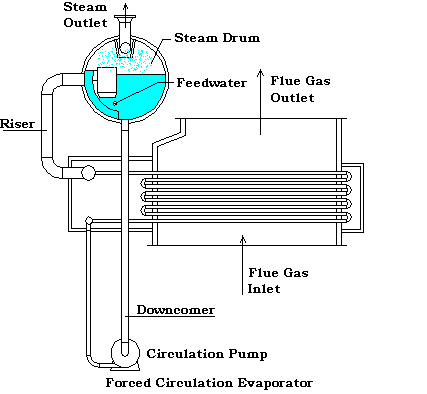
A forced circulation system uses a pump to maintain circulation in all the tubes of the evaporator tube bundle. A typical forced circulation system is shown at the right. The water is distributed within an inlet header to the various parallel circuits and the steam and water mixture is collected in an outlet header. The mixture is returned to a drum for separation of the steam and water.
The tubes may have any orientation but are generally horizontal with an upward water flow to improve stability between the parallel channels. The forced circulation evaporator will generally have more flow resistance than a natural circulation evaporator. In low pressure drop tube bundles, inlet orifices may be required to provide for better distribution to the parallel circuits.
When designing the circultion rate for these HRSG's these factors must be weighed agaist the cost of the pump and the pumping energy. Experience in steam boilers has shown that the "danger" zone in which film boiling can be expected to occur is between 20 and 25 percent steam generation by weight. This has led to the rule of thumb for a 5 : 1 circulation ratio. Unfortunately, this is in fact borderline and does not allow sufficient conservatism for unusual or extreme cases. For instance, an HRSG with a very long horizontal tube length(some units hav been manufactured with tubes as long as a hundred feet).
Also, the relation of the drum to the evaporator coil needs to be considered. As an example a steam coil in a fired heater may have the steam separation drum located a hundred feet away and at the geround, where the coil may be fifty feet up on top of the heater. In this case, the water pressure in the evaporator may be such that instead of total vaporization occuring in the coil, the temperature rises instead, and the major vaporization occurs at the inlet separators in the steam drum. In these cases, a 3 : 1 circulation ratio may be sufficient.
Disclaimer:
The formulas and correlations presented herein are all in the public domain and are to be used only as a learning tool. Note that any product, process, or technology in this document may be the subject of other intellectual property rights reserved by sponsors or contributors to this site. This publication is provided as is, without any warranty of any kind, either expressed or implied, including, but not limited to, the implied warranties of fitness for a particular purpose, or non-infringement.
The formulas, correlations, and methods presented herein should not be considered as being recommended by or used by the sponsors of this site. The purpose of this site is educational and the methods may or may not be suitable for actual design of equipment. Only a fired heater design engineer is qualified to decide if a calculation or procedure is correct for an application.