Heat Balance
The evaporator pinch, or approach temperature, is what limits the amount of heat that can be recovered in most HRSG designs. As was discussed in the previous section, Schematics, the limiting effect of this approach is important. For many general purpose HRSG's such as those found in refineries and chemical plants, a pinch of 50 °F provides an economical design with a realistic payout. But in the more competetive markets of combined cycle or co-generation plants, it is not uncommon to see pinch points below 30 °F. And as a practice, a 30 °F pinch design for these HRSG's should be considered.
It should, however, be remembered that the closer the pinch, or approach, the less reliable the results will be. In other words, it would be easy to calculate the steam generated in a unit at a 5 °F pinch, but the probability of achieving this result with the actual equipment would be almost nil. If you look at the added amount of surface required to go from a 10 °F to a 5 °F pinch versus the change in surface to go from 50 °F to 45 °F, you will quickly see the why this is true.
Other process approach temperatures:Other process appoach temperatures are similar to the special case of the "pinch" discussed above. But, they do not, except in some situations, control the overall design of the HRSG. A 50 °F approach is a good minimum to consider for coils such as hot oil, superheaters, economizers, etc. Of course, the same is true with these coils, the higher the approach temperature, the less surface it will take to exchange the heat. This is why most of the flow in these coils are counter current to the gas flow, which provides a higher approach temperature.
Economizer water approach:The economizer water approach temperature to the evaporator satuaration temperature is very important and should be selected with care. If too close an approach is used in the design, vaporization may occur in the coil during off design cases which may cause severe upsets in the unit. It should be noted, however, that just because the economizer does vaporize at some operating condition, it does not necessarily mean a problem, since the design can be such that it can handle this condition. But, for most designs, it is better to avoid this condition. A normal design approach temperature is 20 °F. This approach gives significant safety factor for load swings. But, again, you should rate HRSG at all expected operating conditions.
Superheated Steam Desuperheating:Superheat desuperheating is the best way to control the outlet temperature of the HRSG superheater. It is not, though, the only way. Steam bypassing around all or part of the superheating coil and then remixing it to control the temperature is done with great success. If a spray desuperheater is used, it can be placed at the outlet, or at an itermediate point in the superheater coil. Placing it at an intermediate point gives the added protection of preventing accidental water slugs which may damage downstream equipment.
Blowdown requirements:The boiler blowdown requirement is set by the condition of the feedwater. Primarily it is used to control solids build up in the steam separation drum. If nothing is known of the feedwater at time HRSG is being designed, an allowance should be used in design. For normal modern facilities, a 2% allowance should be sufficient. For others, a 5% allowance should be provided for in the design. But, you should keep in mind that somewhere along the route from design to production, this must be revisited to assure proper operating conditions in the HRSG.
Developing the Heat Balance for an HRSG:
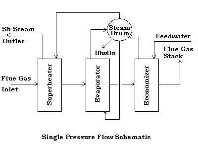
We begin with the first sample schematic that we prepared in Section 3, a single pressure HRSG with a superheater, evaporator, and economizer.
 |
For our process conditions, we will assume the following:
Gas Side : 800,000 lbs/hr of Gas Turbine Exhaust at 980 °F
Setting Loss To Atmosphere, 2% of Heat Absorbed
Maximum Back Pressure at Gas Turbine Exhaust Flange, 8" H2O
| Gas Properties : Volume % | |
| Nitrogen, N2 | 72.55 |
| Oxygen, O2 | 12.34 |
| Carbon Dioxide, CO2 | 3.72 |
| Water, H2O | 10.52 |
| Argon, Ar | 0.87 |
| Sulphur Dioxide, SO2 | 0.0 |
| Carbon Monoxide, CO | 0.0 |
Tube Side : Steam at outlet, Maximum Flow at 600 psig and 750 °F
Feedwater at 227 °F and pressure required at inlet.
| Pinch At Evaporator, °F | 50.0 |
| Economizer Water Approach, °F | 20.0 |
| Blowdown, % of Steam Out | 2.0 |
| Pressure Drop In Superheater, psi | 15.0 |
| Pressure Drop In Economizer, psi | 10.0 |
Now, we have set all of our conditions, so we can proceed with a heat balance. For these calculations, we will need a calculator to provide us with the properties of the flue gas, water, and steam. We can start these in separate windows so we can keep them available as we work out our solution.
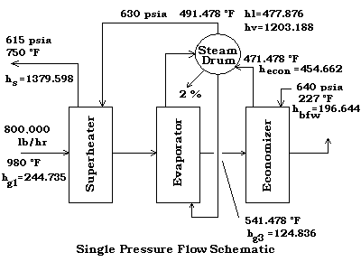
We can now populate our schematic with all known values.
 |
Now we can calculate the missing data.
Heat Available To Evaporator And Superheater:
Resulting in a net heat available of
Heat Required By Steam Flow (To Pinch Point):
But, since Hnet is equal to Hreqd, we can restate the equation as,
= 94038431 / [(1379.598-477.876) + (1 + 2/100) (477.876 - 454.662)]
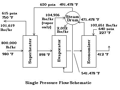
= 101,619 lb/hr
Now that we have the steam flow at the Superheater, 101,619 lb/hr, we can calculate the Superheater heat required, QSH
And the gas enthalpy at the outlet of the superheater coil, hg2
Which results in a gas temperature leaving the superheater of 898.134 °F.
The evaporator duty, QEvap, is equal to,
= 101619 (1203.188 - 477.876) + 101619 (1.02) (477.876 - 454.662) = 76,111,643 Btu/hr
and the steam generated in the evaporator coil, Wevap, is equal to,
Now, we can calculate the Economizer duty, QEcon, as equal to,
= 101619 (1.02) (454.662 - 196.644) = 26,743,922 Btu/hr
And the gas enthalpy at the outlet of the economizer coil, hg4
Which results in a stack gas temperature leaving the economizer of 412.522 °F.
We can now complete our schematic with all known values.
 |
Disclaimer:
The formulas and correlations presented herein are all in the public domain and are to be used only as a learning tool. Note that any product, process, or technology in this document may be the subject of other intellectual property rights reserved by sponsors or contributors to this site. This publication is provided as is, without any warranty of any kind, either expressed or implied, including, but not limited to, the implied warranties of fitness for a particular purpose, or non-infringement.
The formulas, correlations, and methods presented herein should not be considered as being recommended by or used by the sponsors of this site. The purpose of this site is educational and the methods may or may not be suitable for actual design of equipment. Only a fired heater design engineer is qualified to decide if a calculation or procedure is correct for an application.