Preparing a flow schematic for the HRSG
After deciding on the evaporator type to be used for the unit, the next important step in the design of an HRSG unit is to decide the arrangement of the various coils in the unit. Of course, if only an evaporator is present, this may consist of a very simple schematic, but if, as in most cases, there are more than one coil, then consideration needs to be given as to their position in the gas stream.
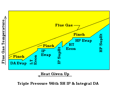
Arrangement of coils.Obviously, the best place to put the highest temperature coil, the superheater, would be in the hottest part of the gas stream. Since, this is where it would take the least amount of surface to exchange the heat, and would allow a stepped heat recovery for maximum heat exchange. The curve below shows this relationship between the heat given up and the three primary coils found in an HRSG.
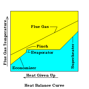 | In viewing this generalized sketch showing the relationship between the heat absorbed and the heat given up, it is easy to see the area referred to as the "pinch" at the evaporator outlet. By laying a straight edge on the heat given up line and rotating it while holding it at the pinch, it is also, easy to see that, at a very high inlet temperature, there may be a critical approach temperature occur at the economizer inlet, and going the other way, at a lower inlet temperature, this may occur at the superheater outlet. |
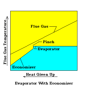
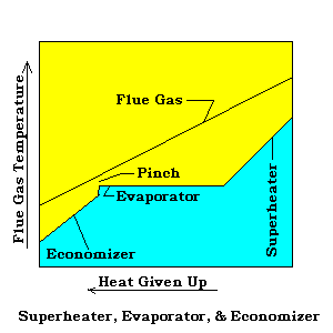
Of course, modern HRSG units are not always this simple. The components can and are placed in many configurations to achieve desired results. The range of arrangements that the coils may be placed, is only limited by the users imagination and the constraints of the temperature approaches. Shown below are just a few examples of various arrangements.
Typical single pressure arrangements.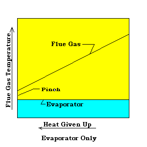 |
 |
 |
| Typical dual pressure arrangements. | 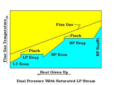 |
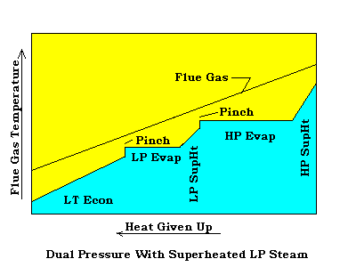 |
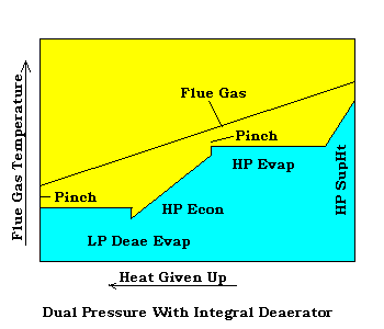 |
Typical triple pressure arrangements.
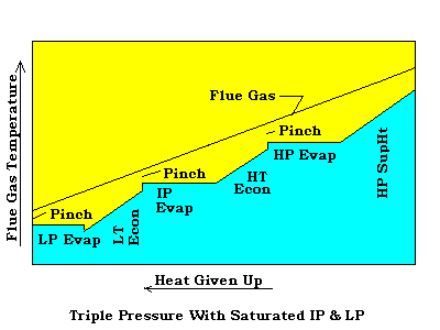 |
 |
Preparing the schematic.
Now that we have a general idea of how to arrange the coils, we prepare the flow schematic. This flow schematic gives us a preliminary picture of how the HRSG will look. Also, we can use the sketch to perform the preliminary heat balance which we will review in Section 4.
For our example flow schematic, we will assume a single pressure HRSG with a superheater and economizer section.
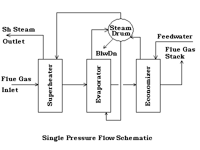 |
It is not important that you necessarily use this style schematic, but it is important to be consistent in the style you use. If you always present an evaporator in the same way, and a superheater always looks like "your" superheater, the flow schematics become very recognizable to anyone needing to refer to them. Remember, the flow schematic does not need to represent the actual mechanical design of the HRSG, neither in looks, or direction of flow, hot to cold, etc.
Now, using a similar approach to above, let's construct a flow schematic to represent a triple pressure unit with an integral deaerator.
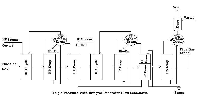 |
Disclaimer:
The formulas and correlations presented herein are all in the public domain and are to be used only as a learning tool. Note that any product, process, or technology in this document may be the subject of other intellectual property rights reserved by sponsors or contributors to this site. This publication is provided as is, without any warranty of any kind, either expressed or implied, including, but not limited to, the implied warranties of fitness for a particular purpose, or non-infringement.
The formulas, correlations, and methods presented herein should not be considered as being recommended by or used by the sponsors of this site. The purpose of this site is educational and the methods may or may not be suitable for actual design of equipment. Only a fired heater design engineer is qualified to decide if a calculation or procedure is correct for an application.