Types and Configurations of HRSGs
| D-Frame evaporator layout |
| O-Frame evaporator layout |
| A-Frame evaporator layout |
| I-Frame evaporator layout |
| Horizontal tube evaporator layout |
| Superheater configurations |
| Economizer configurations |
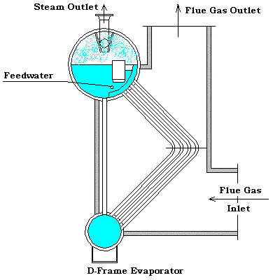 | D-Frame evaporator layout. This configuration is very popular for HRSG units recovering heat from small gas turbines and diesel engines. It is a very compact design and can be shipped totally assembled. It is limited, however, since the bent tube arrangement quickly causes the module to exceed shipping limitations for units having a large gas flow. |
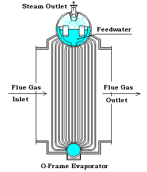 | O-Frame evaporator layout. This configuration has probably been used for more years than any of the others. It has the advantage of the upper header being configured as the steam separation drum. Or, the upper header can be connected to the steam drum by risers, allowing more than one O-Frame evaporator to be connected to the same steam drum, resulting in shipable modules being able to handle very large gas flows. |
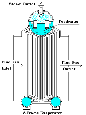 | A-Frame evaporator layout. This configuration is simply a variation of the O-Frame Evaporator. It was popular for services with a large amount of ash, since the center area between the lower drums could be configured as a hopper to collect and remove solid particles. |
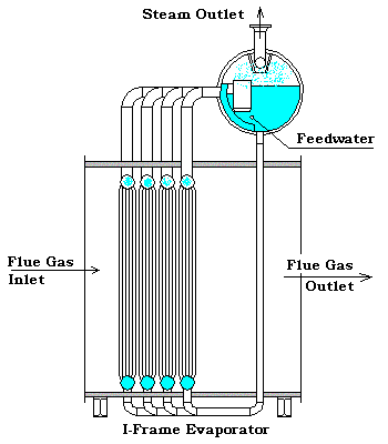 | I-Frame evaporator layout. In the past twenty years, this configuration has become the most popular of all the Evaporator designs. This type module can be built in multiple axial modules or in multiple lateral modules, allowing it to be designed to accept any gas flow. There are numerous variations of this design where tube bundles may contain one, two, or three rows of tubes per header. It is also, normally, more economical to manufacture, ship and field construct. The tube bundles may be shipped to field installed in the modules, or as loose bundles which are installed into a field erected shell. |
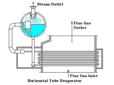 | Horizontal tube evaporator layout. The horizontal tube evaporator is used, not only for heat recovery from Gas Turbine exhaust, but for recovery from flue gases in Refinery and Petrochemical furnaces also. It has similar size limitations due to shipping restrictions similar to the O-frame modules. It is generally a less expensive unit to manufacture than the other configurations, but if it is a natural circulation design with large tubes, such as in some CO Boilers, or very long tubes, special consideration needs to be given to assure all tubes are provided with sufficient effluent. These considerations will be discussed later on in this document. |
Superheater configurations.
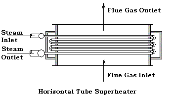
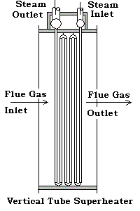
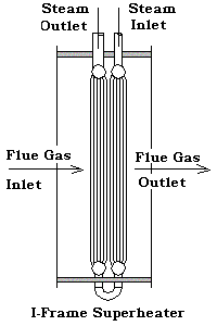
Superheater designs would normally follow along with the evaporator type that is being used. Three basic superheater designs are shown below, Horizontal Tube, Vertical Tube, and I-Frame. The Horizontal Tube design would normally be used for the D-Frame Evaporator if gas flow is vertical up at the outlet. This horizontal design would be expected to be used also on a horizontal evaporator design. The Vertical Tube design would generally be used with the A-Frame or O-Frame Evaporator and with the D-Frame if the gas exits horizontally. The I-Frame Superheater would be used with the I-Frame Evaporator, but may also be used with the other evaporator designs.
 |
 |
 |
Economizer configurations.
Economizer designs would normally follow along with the evaporator type that is being used and be similar in design to the superheater. The configurations would be similar to the ones shown above for the superheaters.
Disclaimer:
The formulas and correlations presented herein are all in the public domain and are to be used only as a learning tool. Note that any product, process, or technology in this document may be the subject of other intellectual property rights reserved by sponsors or contributors to this site. This publication is provided as is, without any warranty of any kind, either expressed or implied, including, but not limited to, the implied warranties of fitness for a particular purpose, or non-infringement.
The formulas, correlations, and methods presented herein should not be considered as being recommended by or used by the sponsors of this site. The purpose of this site is educational and the methods may or may not be suitable for actual design of equipment. Only a fired heater design engineer is qualified to decide if a calculation or procedure is correct for an application.