Scope and Definition of HRSGs
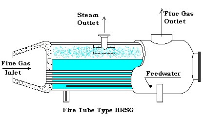
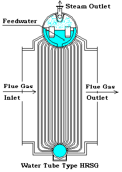
The Heat Recovery Steam Generator, or HRSG, comes in numerous shapes, designs, configurations, arrangements, etc. To simplify our discussion herein, we will first state that the type of HRSG we are reviewing is what may be referred to as a water tube(as opposed to a fire tube) type heat recovery unit. This refers to the process fluid, i.e., the steam or water being on the inside of the tube with the products of combustion being on the outside of the tube. The products of combustion are normally at or close to atmospheric pressure, therefore, the shell side is generally not considered to be a pressure vessel.
 |
 |
Definition of concepts and terminology used in discussions.
In the design of an HRSG, the first step normally is to perform a theoretical heat balance which will give us the relationship between the tube side and shell side process. Before we can compute this heat balance, we must decide the tube side components which will make up our HRSG unit. Even though these components may include other heat exchange services, at this time we will only consider the three primary coil types that may be present, i.e., Evaporator, Superheater, Economizer. When we refer to an Evaporator Section, this includes all the evaporator coils making up the total evaporator for a Pressure System. A pressure system includes all the components included in the various streams associated with that pressure level.
Evaporator SectionThe most important component would, of course, be the Evaporator Section, since without this coil(or coils), the unit would not be an HRSG. Throughout our discussion, we will refer to a main heat transfer component as a "section". When the section is broken into more than one segment, i.e., such as for a change in tube size, material, extended surface, location, etc., we will refer to the segments as coils. So an evaporator section may consist of one or more coils. In these coils, the effluent(water), passing through the tubes is heated to the saturation point for the pressure it is flowing.
Superheater SectionThe Superheater Section of the HRSG is used to dry the saturated vapor being separated in the steam drum. In some units it may only be heated to little above the saturation point where in other units it may be superheated to a significant temperature for additional energy storage. The Superheater Section is normally located in the hotter gas stream, in front of the evaporator.
Economizer SectionThe Economizer Section, sometimes called a preheater or preheat coil, is used to preheat the feedwater being introduced to the system to replace the steam(vapor) being removed from the system via the superheater or steam outlet and the water loss through blowdown. It is normally located in the colder gas downstream of the evaporator. Since the evaporator inlet and outlet temperatures are both close to the saturation temperature for the system pressure, the amount of heat that may be removed from the flue gas is limited due to the approach to the evaporator, known as the pinch which is discussed later, whereas the economizer inlet temperature is low, allowing the flue gas temperature to be taken lower.
Disclaimer:
The formulas and correlations presented herein are all in the public domain and are to be used only as a learning tool. Note that any product, process, or technology in this document may be the subject of other intellectual property rights reserved by sponsors or contributors to this site. This publication is provided as is, without any warranty of any kind, either expressed or implied, including, but not limited to, the implied warranties of fitness for a particular purpose, or non-infringement.
The formulas, correlations, and methods presented herein should not be considered as being recommended by or used by the sponsors of this site. The purpose of this site is educational and the methods may or may not be suitable for actual design of equipment. Only a fired heater design engineer is qualified to decide if a calculation or procedure is correct for an application.