Shield Section Design
This section of Fired Heater Design is divided into three main areas, which can be selected from the subject drop down box above or you may use the jump links below to go to a section. You may also use your browser "back button" to return to where you were.
| Direct Radiation In The Shield Section | ||
| Indirect, Non-Luminus Radiation In The Shield Section | ||
| Shield Section Rating |
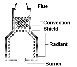
 | In a heater similar to this one, the lower rows are directly exposed to the hot gasses and flame in the radiant section. To calculate the heat transfered to these tubes by radiation, we use the same formula that we did in the radiant section. |
| qS = Radiant heat transfer to shield, Btu/hr |
| s = Stefan-Boltzman constant, 0.173E-8 Btu/ft2-hr-R4 |
| a = Relative effectiveness factor of the tube bank |
| Acp = Cold plane area of the tube bank, ft2 |
| F = Exchange factor |
| Tg = Effective gas temperature in firebox, °R |
| Tw = Average tube wall temperature, °R |
Relative Effectiveness Factor, a :
Since all the heat directed toward this bank of tubes, leaves the radiant section and is absorbed by the tubes, the relative absorption effectiveness factor, a, for the shield tubes can be taken to be equal to one.
Cold Plane Area, Acp :The cold plane area for the shield section is equal to the cold plane area of the first row of tubes.
Acp = Ntube*Stube*LtubeWhere,
Ntube = Number of tubes wide
Stube = Tube spacing, ft
Ltube = Tube length, ft
Exchange Factor, F :
Effective gas temperature in firebox, Tg
Average tube wall temperature, Tw
The values used for these factors are the same as the values to be used in the radiant section. The difference is, when there is a shield section, which is receiving direct radiation, the aAcp for the radiant and the shield are calculated independently, then added together to calculate the exchange factor, F.
So the equation for Aw, becomes:Aw = Ar - ((aAcp)rad + (aAcp)shld)
And for Aw/aAcp,
Aw/aAcp = Aw/ ((aAcp)rad + (aAcp)shld)
| Where, |
| Aw = Effective refractory area, ft2 |
| Ar = Total refractory area, ft2 |
| (aAcp)rad = Equivalent cold plane area of radiant tubes, ft2 |
| (aAcp)shld = Equivalent cold plane area of shield tubes, ft2 |
And total transfer to radint tubes,
And radiant only transfer to shield tubes,
NOTE: It should be noted here, that the convective transfer, qc, for the radiant section remains as it was described and it does not apply to the shield tubes. The convection transfer to the shield tubes is calculated the same as for other convection tubes. It is also, important to remember that the Tg applies to the gas temperature after the shield radiant heat is removed, but before the shield convection heat is removed.
Now that we have calculated the direct radiant transfer to the shield tubes, how do we apply it? The heat can be distributed to the first two rows using the proportions equivalent to the alpha factor curve for direct to first row compared to total to two rows. This results in approximately 77% to the first row and 23% to the second. This assumption would appear to be sufficient, even though some of the radiant heat would also be directed to the third row. But the amount going to the third row would be small and this approach is conservative, since it would assume more heat in the first two rows where high tube fluxs and wall temperatures could be a problem.
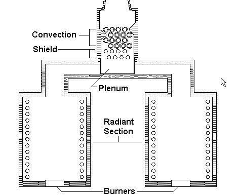
 | In a heater similar to this one, the lower rows are not directly exposed to the hot gasses and flame in the radiant section. However they are exposed to the heat radiated off the refractory lined plenum beneath the tubes. To calculate the heat transfered to these tubes by radiation, we use the same formula that we did in the radiant section. |
| qn = Non-luminous radiant heat transfer to the shield, Btu/hr |
| s = Stefan-Boltzman constant, 0.173E-8 Btu/ft2-hr-R4 |
| a = Relative effectiveness factor of the tube bank |
| Acp = Cold plane area of the tube bank, ft2 |
| F = Exchange factor |
| Tg = Effective gas temperature in firebox, °R |
| Tw = Average tube wall temperature, °R |
Relative Effectiveness Factor, a :
Since all the radiant heat directed toward this bank of tubes is absorbed by the tubes in the convection, the relative absorption effectiveness factor, a, for the shield tubes can be taken to be equal to one.
Cold Plane Area, Acp :The cold plane area for the shield section is equal to the cold plane area of the first row of tubes.
Acp = Ntube*Stube*LtubeWhere,
Ntube = Number of tubes wide
Stube = Tube spacing, ft
Ltube = Tube length, ft
Exchange Factor, F :
Effective gas temperature in firebox, Tg
Average tube wall temperature, Tw
The values used for these factors are calculated the same way as was described in the radiant design section. The Ar factor being the only exception. This factor is the inside area of the plenum below the tubes. The openings where the flue gas enters are normally ignored, since the ducting connecting them perform the same reflective purpose.
This type of shield calculation is totally independent of the radiant section where the heat balance is performed as if there where no shield. The radiant heat from this calculation will reduce the gas temperature used in the convection transfer calculation.If we use our example from the radiant section design, and we add two rows of shield tubes, we would have something like the following:
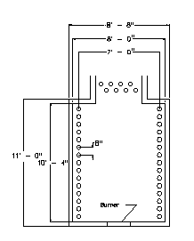
| Process Conditions: Heat Absorbed, Btu/hr = 9,500,000 Tube Wall Temperature, °F = 600 Fuel(Previous example fuel) = Gas Excess Air, % = 15 Radiant Mechanical Conditions: Tube Diameter, in = 4.500 Tube Spacing, in = 8 Tube Effective Length, ft = 26.000 Number Of Tubes = 30 Radiant Arrangement = Box Shield Mechanical Conditions: Tube Diameter, in = 4.500 Tube Spacing, in = 8 Tube Effective Length, ft = 26.000 Number Of Tubes = 8 Tubes Per Row = 4 |
 |
In our previous radiant example, we calculated the following values for our radiant heat transfer:
| qr = Radiant heat transfer, Btu/hr |
| s = 0.173E-8 Btu/ft2-hr-R4 |
| a = 0.915 |
| Acp = 520.0 ft2 |
| F = 0.585 |
| Tg = 2063, °R |
| Tw = 1060, °R |
But, as we have reviewed in the shield design, we must now recalculate the exchange factor, F, which will change our gas exit temperature, Tg, as well.
Aw/((aAcp)rad + (aAcp)shld)The Aw can be described as follows,
| Aw = Ar - ((aAcp)rad + (aAcp)shld) |
| and, |
| Aw = Effective refractory area, ft2 |
| Ar = Total refractory area, ft2 |
| aAcp = Equivalent cold plane area, ft2 |
Ar = 8*10.333*2+8*26*2+10.333*26*2-69.333 = 1049 ft2
(aAcp)rad = 0.915*30*8/12*26 = 475.8 ft2
(aAcp)shld = 1.0*4*8/12*26 = 69.333 ft2
so,
Aw = 1049 - 475.8 - 69.333 = 503.867
and,
Aw/((aAcp)rad + (aAcp)shld) = 503.867/(475.8+69.333) = 0.9243
The beam length will remain the same as the previous example, since we have not changed our firebox size.
The partial pressure of the flue gas will remain the same since flue gas composition has not been changed.
The emissivity, however, does change since it is dependent on the temerature of the gas, Tg.
You may wish to go back to the radiant section and review these calculations in detail, at this time. If not, select the button below to open a window where we can do a few calculations to see the results of adding a shield section.
Disclaimer:
The formulas and correlations presented herein are all in the public domain and are to be used only as a learning tool. Note that any product, process, or technology in this document may be the subject of other intellectual property rights reserved by sponsors or contributors to this site. This publication is provided as is, without any warranty of any kind, either expressed or implied, including, but not limited to, the implied warranties of fitness for a particular purpose, or non-infringement.
The formulas, correlations, and methods presented herein should not be considered as being recommended by or used by the sponsors of this site. The purpose of this site is educational and the methods may or may not be suitable for actual design of equipment. Only a fired heater design engineer is qualified to decide if a calculation or procedure is correct for an application.