Procedure for Fired Heater Design
Guidelines for Vertical Cylindrical Fired Heater Design
The guidelines and procedures included herein are appropriate for a typical direct fired heater of the types found in refineries and gas plants, and is not expected to include specialty heaters or furnaces that include reaction in the tubes due to heat or catalysts. We will assume that for this discussion that the heater design will need to meet API 560 and API 530 standards.
For this first example of selecting a heater design, we will assume the heater is a small unit of the type used in the Petro‐Chemical industry.
Considerations of plot area: The area available to place the new unit is one of the first items to be considered, and often leads to the determination of the heater configuration selected. If the plot area is very small, frequently this leads the designer to select a vertical cylindrical heater design since the area required is much smaller, than an equivalent horizontal tube heater.
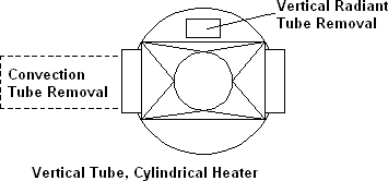
Vertical Cylindrical Heater plan view‐
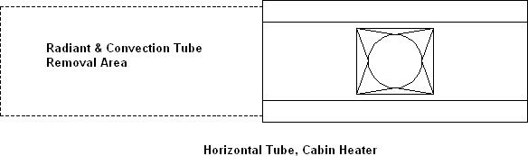
Horizontal Tube Heater plan view‐
Shipping sizes and considerations: No matter what the heater configuration or overall size of the heater, it is important to know the method that will be used and the shipping piece size that can be cleared. If the heater is small, say less than 40 MM Btu/hr, then the design should be something that can clear in one piece for cylindrical radiant section or one or two vertical pieces for a horizontal tube design. For larger furnaces, it is important to always keep in mind during the design, how best to split the pieces for shipment. The reason for this is that it is normally lower cost to fabricate as much as possible in the shop while minimizing the field work to assemble final unit.
Basic data needed for heater design: The minimum amount of data needed to create a heater design would be as follows:
- Heater duty to be absorbed by the heater
- Process Flow to the heater
- Inlet and outlet conditions temperature
- Outlet pressure
- Pressure drop allowed
- A property grid of process transport properties or as a minimum, the approximate inlet and outlet properties including thermal conductivity, viscosity, and specific heat.
- If the process fluid is mixed phase, then you will need to use a data grid to get a meaningful calculation for the pressure drop, especially if it is all liquid at inlet and mixed phase at outlet, since the thermal design program would have no way to determine where vaporization begins without a data grid.
- Fuel Data including the composition, if gas, and if liquid, the lower heating value and method of atomization to be used as well as conditions of air or steam if used for atomizing.
- Site specific data such as ambient temperature and elevation.
- Target or maximum tube flux in the radiant section.
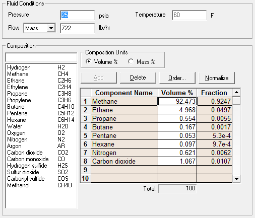
For the purpose of demonstrating the methods below, we will assume a heater is required to meet the following data:
- Service – Water Heater
- Duty – 12,730,300 Btu/hr
- Flow – 154,475 lb/hr
- Outlet Pressure – 85 psia
- Pressure drop allowed – 15 psi
|
Description |
Inlet conditions |
Outlet Conditions |
|
Percent Vapor, % |
0 |
0 |
|
Specific Gravity |
0.9552 |
0.9172 |
|
Viscosity, Cp |
0.2651 |
0.1811 |
|
Specific Heat, Btu/lb‐F |
1.0081 |
1.0293 |
|
Conductivity, Btu/hr‐ft‐F |
0.3950 |
0.3971 |
- Site Ambient Temperature – 80 °F
- Site Elevation – Sea Level
- Target Average Radiant Flux Rate – 10,000 to 12,000
- Target Efficiency – 85 to 87 %
- Burners Natural Gas, Low NOx configuration
- Fuel to have the following composition, % Volume:
- CH4 92.473
- C2H6 4.968
- C3H8 0.554
- C4H10 0.167
- C5H12 0.053
- C6H14 0.097
- N2 0.621
- CO2 1.067
Radiant Configuration Selection: For the first example, we will say that plot limitations make the Vertical Tube Cylindrical Design more attractive.
Preliminary estimate of surface in radiant section: To begin a design, you can assume that approximately 70% of the heat to be absorbed will be absorbed in the radiant section, and the remainder in the convection section.
Approximate surface = 0.70 * 12730300 / 10000 = 891 ft2
Deciding the initial tube size and layout: Since 4” nominal pipe size is normally the lower cost material and the most available pipe for a typical service, it is a good place to start.
(4.5” dia. * Pi * 12”)/ 144 = 1.178 ft2/ft is the area per foot of pipe 891/1.178 = 756 ft of 4” nominal pipe required for radiant section
So if we were going to design this heater as a vertical tube cylindrical heater, we would need to rough out the tube circle and tube length to start with.
We will start with a radiant section containing 30 tubes. Then the approximate effective length of the tubes would be 756/30 = 25.2 ft.
For the spacing of the tubes, we would use the rule of thumb, 2 * nominal tube diameter or 8” or 0.6667 ft. Note that the API 560 states that the average flux is normally based on a 2 nominal tube diameter spacing, but does not require this spacing. The 8” tube spacing also meets the API 560 table of allowed spacing.
The actual tube circle calculation is a little complicated, as we will see later, but for now we can use the approximation of no. of tubes * spacing / pi or 30 * 0.6667 / 3.1412 = 6.3702 ft.
The distance from floor to roof can be approximated at 25.2 ft tube length + 1.0 ft = 26.2 ft.
Since API 560 requires this type of heater to have an L/D ratio of less than 2.75, and our first sizing gives 26.2/6.3702 = 4.1129 then we know that we need to increase the number of tubes.
If we use 38 tubes, then the tube circle becomes 8.0653, and the effective tube length would be 19.8947 ft, so approximate height = 20.8947 ft, and L/D = 2.59, which meets the API 560 requirement.
Convection Section Preliminary Sizing: At this time we only need to consider the number of tubes wide and the effective length that we want initially to start the design.
The effective length can vary depending on final heat transfer calculations, but a rule of thumb for this length on a vertical cylindrical design is to start with the tube circle dimension, rounded up to an even 3 or 6 inches, in this case 8.25 ft.
For the number of tubes wide, you would normally start with 4, and then go more or less as may be needed during thermal design runs.
The tube length and tubes wide need to take into account the convection box overhang, and space required for crossovers, radiant tube pulling doors, etc.
API 560 requires that the shield (shock) tube section has 3 rows deep. The shield section always uses bare tubes. API 560 requires the first row flux to be included in the average heat flux density of the radiant section.
The remainder of the convection section tubes may be bare or with extended surface. Per API 560, the convection section must be designed to allow for two future rows of tubes. This code also requires that the convection section be designed with lanes for soot blowing, steam lancing or water washing, and these lanes must consider the future row requirement.
The convection section must be designed with corbels to minimize flue gas bypassing. API 560 does not specify how this design is to be accomplished, but the normal practice is a minimum of a corbel every other row. If the convection has end covers instead of tube sheets, then the return and bare tube beyond extended surface would be corbelled.
Since heater efficiency is very much enhanced with extended surface tubes, for our design, we will assume four rows of extended surface tubes.
Number of tube side passes: The number of tube side passes or flow streams in the heater will be assumed as two. This will be increased or decreased during thermal design to meet pressure loss requirements.
Burner selection: Since these guidelines are written to assist a user in developing a new heater design, it is assumed that the burner selection cannot be made until after or during the thermal design. At that time, the selection of burners, quantity to be used, and burner spacing from tubes will be considered.
Thermal design of the heater:
To input into the thermal rating program, Xfh, we need to calculate the actual tube circle diameter, which can be done using the following formula.
Dtube = ((TubeSpace/2)/Sin(pi/NoTubes))*2/12 = ((8/2)/Sin(Pi/38))*2/12 = 8.073 ft
We will use wrought return bends for this heater, which is common practice. The return bend with a center to center of 8“, would have an effective length 8 * Pi /12/2 = 1.0471’.
So the straight tube length would equal 19.8947 ‐ 1.0471 = 18.8476’, which is well below the API 560 maximum of 60’ for this type furnace.
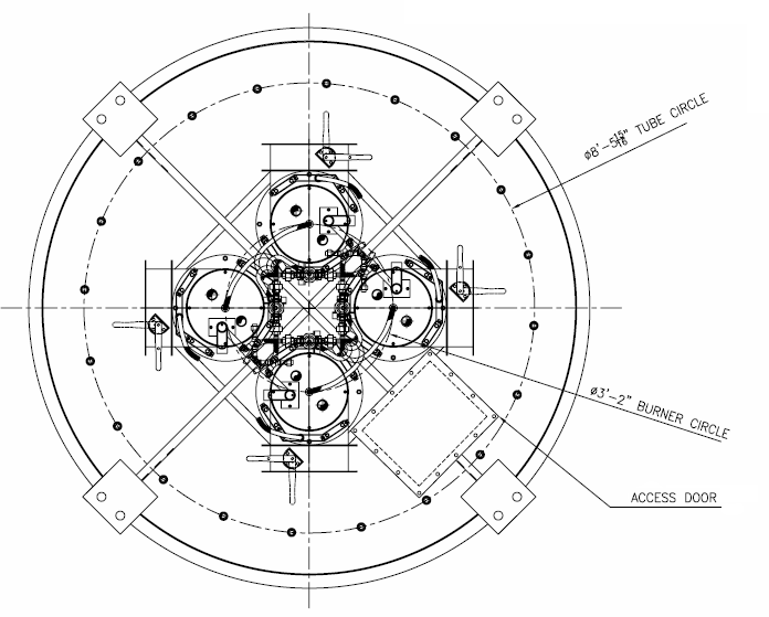
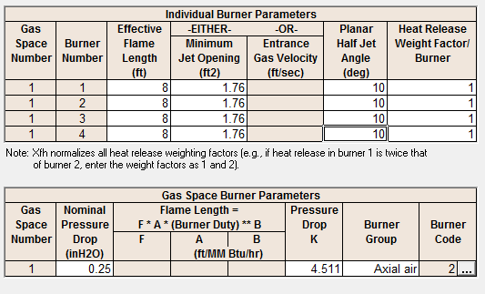
For the first run we will consider 4 burners on a 3 ft burner circle, with 10° half jet angle and 12 in dia. Flame length will be assumed at 2 ft/MM Btu/hr.
It should be noted that it is normally preferable to use more burners, rather than less to get more consistent heat flux in the radiant section. For this reason, you would never want to use only two burners in a cylindrical heater. Also, in this type furnace, the more burners, the less the centerline to centerline spacing requirement.
If we assume the efficiency of the heater is to be 85 %, then the total release from the burners will be approximately 12,730,300/0.85 = 14,976,824 Btu/hr. With our selection of 4 burners, this would be 14976824/4 = 3,744,206 Btu/hr each burner. For a heater with 5 or less burners, API 560 requires the burner maximum design to be 1.25% of normal release, or 3744206 * 1.25 m= 4,680,258 Btu/hr.
For this size burner, API 560 requires a minimum of 2.667 ft (interpolated from table) from centerline of burner to centerline of tube. For our preliminary design, this dimension is (8.073‐3.0)/2 = 2.5365’.
Revised Tube Circle:
Therefore to meet the burner to tube spacing, we will increase the number of radiant tubes to 40, which results in a tube circle of 8.497’, and a centerline of burner to centerline of tube dimension at 2.7485’, which will meet the API requirement.
To allow as much centerline to centerline between burners as we can, we will adjust the burner circle out to the maximum that will meet the burner to tube limit, or 8.497‐2.667*2 = 3.163’ burner circle.
Revised Straight Tube Length:
This will require us to adjust our straight tube length to 17.853’ in the radiant section. Also, we will adjust out convection effective tube length to the new tube circle dimension, or approximately 8.5’.
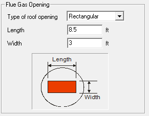
Flue Gas Opening To Convection Section:
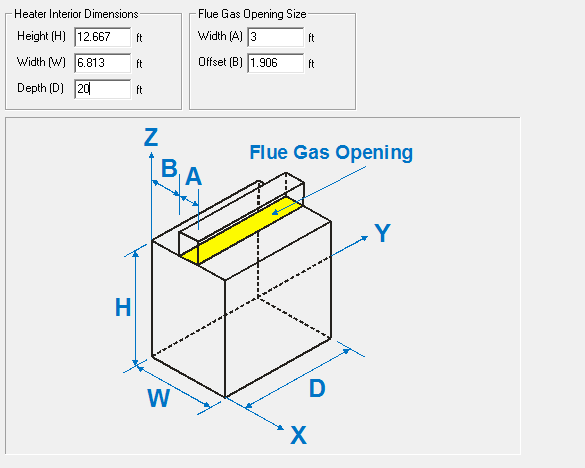
The length and width of the flue gas opening in roof of radiant would be: Length = Effective Length of convection tubes = 8.5 ‘
We will assume we will use triangular pitch tubes for this heater in convection to get better heat transfer.
Width = (tubes wide + ½) * spacing = 4.5 * 8/12 = 3.0 ‘
We will set the oxidant to air at 20 % excess air, as required by API 560. We will set fuel flow to be determined by Duty of 12,730,300 Btu/hr
We will select A106 Gr. B tube material for this service, which meets the requirements of API 560.
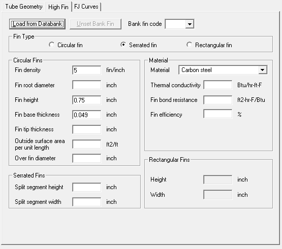
For the convection tube extended surface tubes, we will choose 3/4” high x 0.049” thick x 5 fins/inch serrated fins which will meet the API 560 requirements, for a gas fired heater.
As previously indicated, we will start with 4 rows of extended surface tubes plus 3 bare rows of shock tubes. With the API 560 requirement for future rows, this will give us a total of 9 rows. For the required cleaning lane, we will place between row 5 and 6 since the first three rows are bare, and we would then be cleaning two finned rows down and two up.
Inside Radiant Dimensions:
Tube Circle = 8.497’
Refractory inside diameter = 8.497’ + 1.5 Nominal Diameters per API 560 * 2 = 9.497’
API 560 requires a minimum clearance from tube to refractory of 4”, where the basic rule above only has, Space‐TubeDia/2 = 6 – 4.5/2 = 3.75”, so the inside diameter will need to be set at 8.497’ + 2* 6.25/12 = 9.5387’.
We will use a bottom tube support for this design, as it will be more economical than a top tube hanger, as well as offering several other advantages as noted below.
Since only the support washer needs to be stainless material, the cost of the support is lower than a hanger. Also, a nut can be screwed on end of guide to hold coil in place during shipment, since the radiant section will need to be laid on its side in saddles for shipping.
We can assume the washer to be 3/8” thick.
With a bottom support, we will need to add an allow tube guide at the upper portion of the tubes, similar to below.
Each guide will hold two tubes in position and allow them to grow vertically. The typical guide below meets API 560 radiant guide requirements that a guide can be replaced with removing the tubes and with minimal refractory damage.
The dimension from the inside floor surface to top of the upper returns will then be, 0.375” + 2.25” + 4” + 17.853 * 12 + 4” + 2.25” = 227.111”
For thermal expansion of tube and for handling during tube removal, we will allow 6” of clearance from top of return to refractory, which will result in an inside height of 19.426’.
Refractory System:
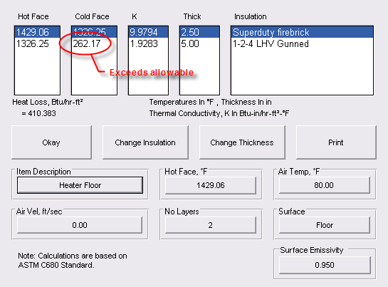
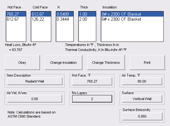
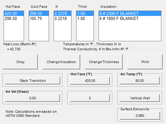
For our initial design, we will use the following refractory system. API 560 requires the outside casing not to exceed 180 °F with zero wind and 80 °F ambient temperature. The radiant floor can be 195 °F.
With this in mind, we will assume the following ( All meeting API560):
Radiant Floor ‐ 2.5” Firebriick + 5” 1‐2‐4 LHV (meets API 560)
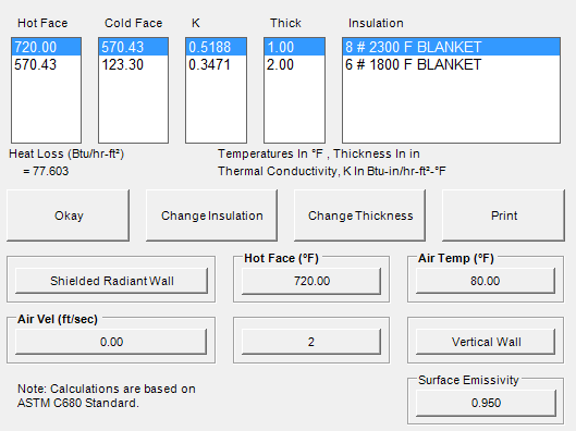
Radiant Walls (shielded)‐ 1” 8# + 2”6# Ceramic Fiber
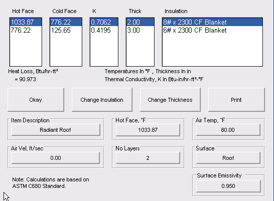
Radiant Roof ‐ 2”8#+3”6# Ceramic Fiber
Convection Walls ‐ 1”8#+2”6# Ceramic Fiber
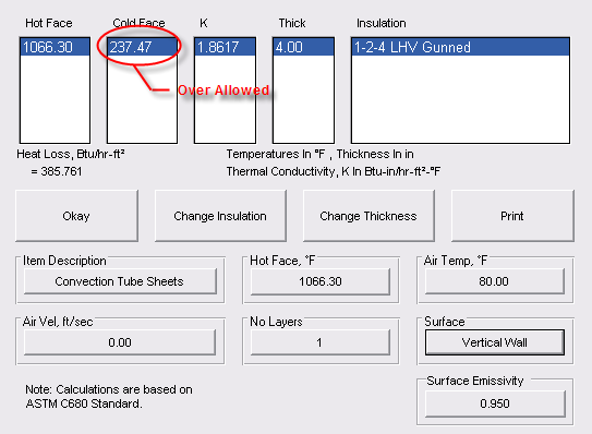
Convection Tube Sheets ‐ 4” 1‐2‐4 LHV (meets API 560)
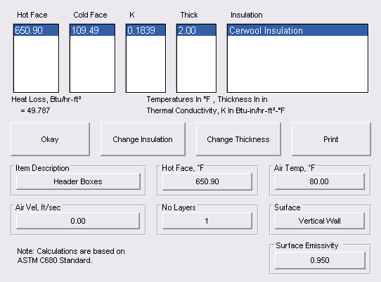
Header Boxes ‐ 2” Cerwool
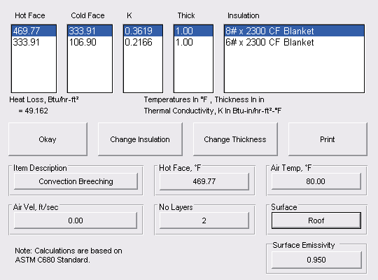
Convection Breeching ‐ 1”8#+1”6# Ceramic Fiber
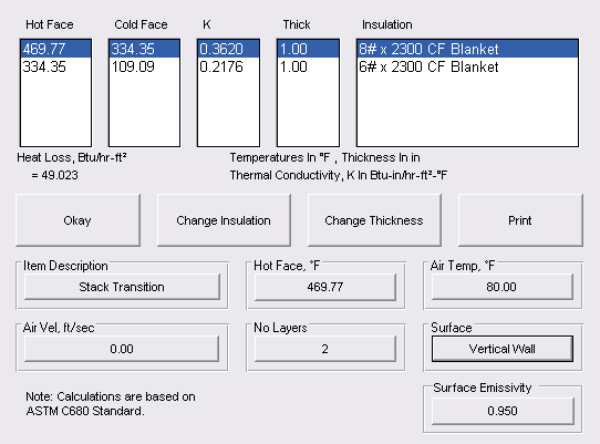
Stack Transition ‐ 1”8#+1”6# Ceramic Fiber
Stack – Unlined since at this efficiency temperature will be between 400 ° F and 700 °F as allowed by API 560
Plate Thicknesses:
We will assume the following plate thicknesses, which will be ultimately checked by structural engineer.
Radiant Floor – ¼”
Radiant Walls – ¼”
Radiant Roof – ¼”
Convection Walls – 3/16”
Convection Tube Sheets – ½” (meets API 560)
Convection Breeching – 3/16”
Stack Transition – ¼”
Stack – ¼”
Outside Radiant Dimensions:
Outside diameter = 9.5387’ + (3.25 * 2)/12 = 10.0804’
Outside Height = 19.426 + 5.25/12 + 7.75/12 = 20.5093’
Wall Thickness = 3” + ¼” = 3.25“ Roof Thickness = 5” + ¼” = 5.25 “
Floor thickness = 5” + 2.5” + ¼” = 7.75”
Check Volumetric Heat Release:
Burner Chamber = 8.497’
Volume = 8.497 * 8.497 * Pi / 4 * 19.426 = 1,102 ft3
Volumetric Heat Release = 14,976,824/1102 = 13,590 Btu/hr‐ft3 which is less than the 16,000 Btu/hr‐ft3 allowed by API 560.
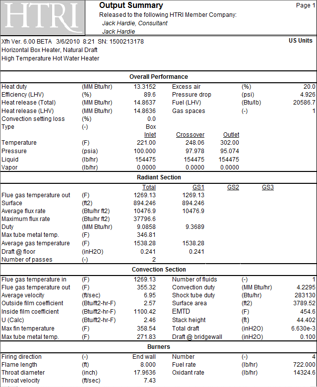
Our Initial Thermal Design Run:
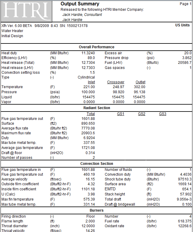
Our pressure drop is okay, so no need to modify tube passes. If we tried to go down to 1 pass, we would exceed allowed, so two pass is best fit.
Our flux rate is low and below target, and our efficiency is better than target, so we should consider reducing the tube length since we have more height than we need.
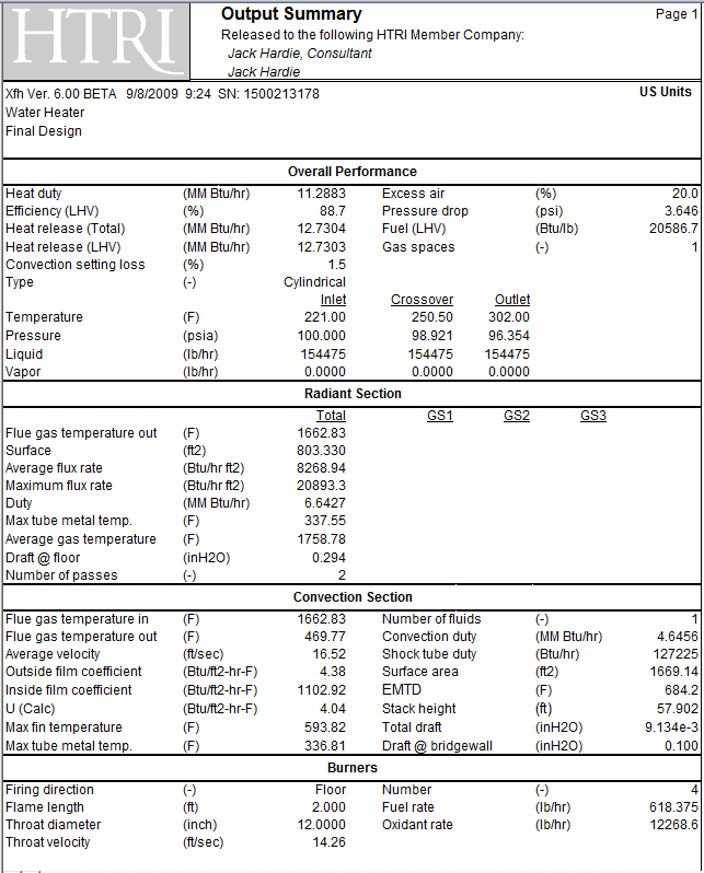
If we reduce the tube length to 16’ straight length, we will still have height to meet API 560, vertical distance to refractory requirement. This will make the L/D approximately 2 which is about as low as you would want for this type furnace. So even though our flux rate is below target and our efficiency is above, this appears to be a good design for this project.
Stack Design:
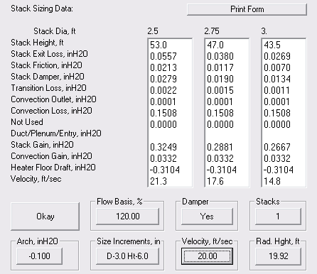
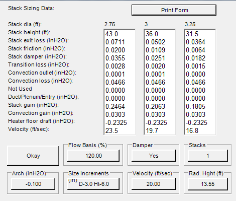
API 560 [2.2.5] requires stack to be designed to achieve ‐0.10 at the arch of heater to assure negative pressure throughout. This design is to be based on 120 % of burner release, design excess air and design stack temperature, and maximum ambient air temperature. Normal practice is to use approximately 20‐ 25 ft/sec velocity in stack.
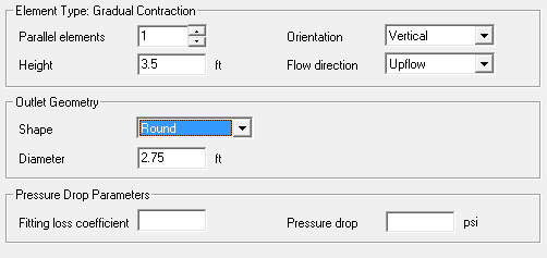
At 120 % burner release and design excess air, the flue gas flow will be 15,464 lb/hr and the stack temperature will be 470 °F. Ambient air temperature is 80 °F. Since the stack is relatively tall for a small diameter, I chose to use the larger diameter of 2.75 feet for the inside diameter.
To recheck the burner sizing and spacing, the total release per our last run is 12.7303 MM Btu/hr , and the release per burner will be 12.7303/4 = 3.1826 MM Btu/hr. Per API 560, the size for each burner will be 3.1826 * 1.25 = 3.9782 MM Btu/hr. So the required horizontal spacing is 2’ – 6”. Our tube circle is 8.497’, so our burner circle will be 8.497 – 2*2.5’ = 3.497’ or 3’‐ 5 15/16“.
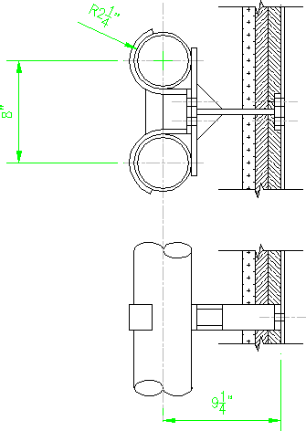
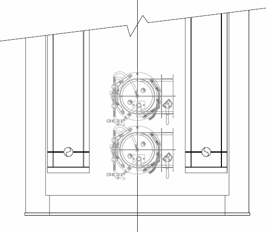
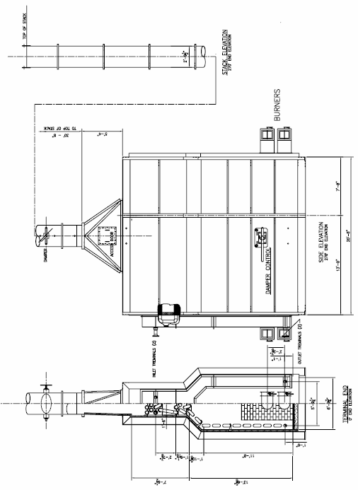
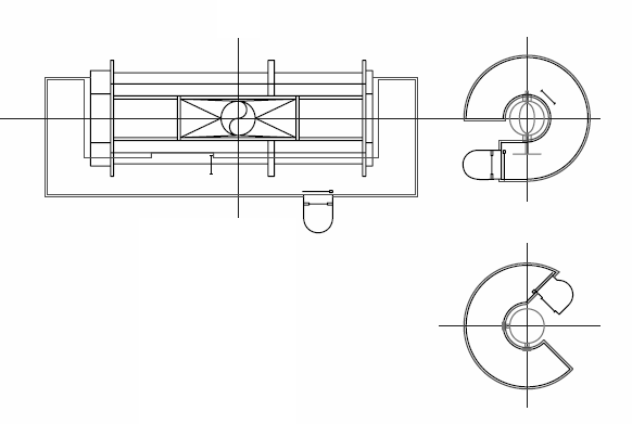
A layout of the floor with a typical burner design and adding typical steel support and base plates, would look similar to below:
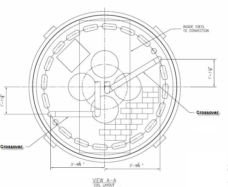
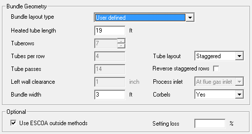
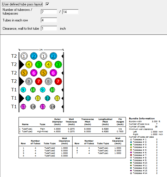
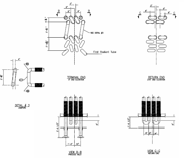
To determine the tubes, fittings and finning needed for the design, we will use a simple layout of the coils. The convection coil would be as shown. Notice, that per API 560 we needed to include a cleaning lane or soot blower lane in the design.
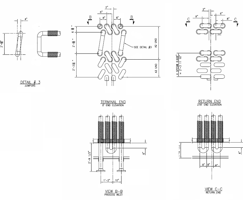
The radiant to convection crossover piping can best be shown in a section view.
And the radiant tubes in a flat panel
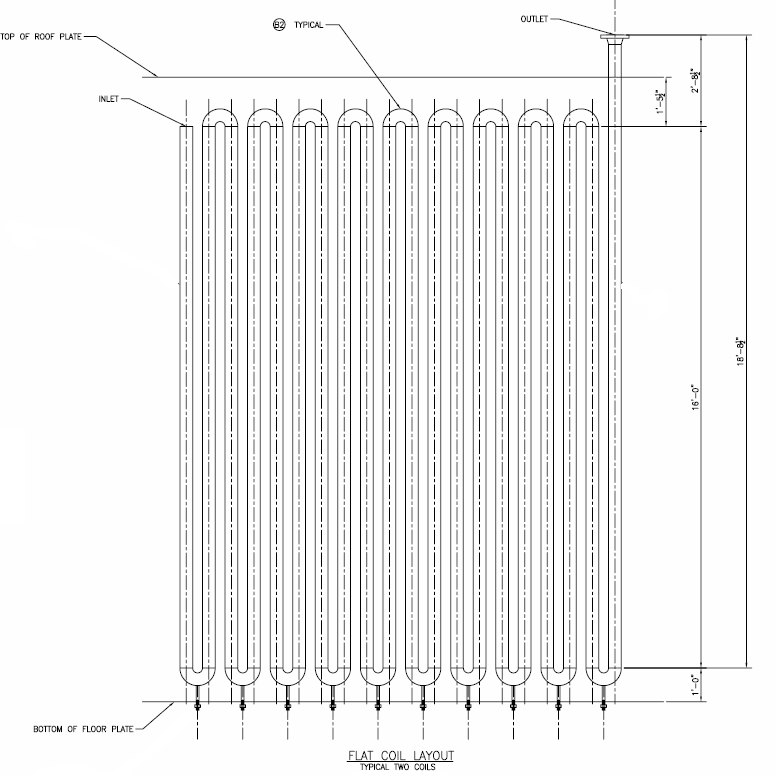 layout.
At this point in the design of the fired heater, a general arrangement drawing would normally be created giving the overall dimensions of the heater and indicating the insulation to be used in the different areas. The structural steel at this point is simply added to the drawing based on previous designs of similar heaters. After the thermal and mechanical design has been completed, the general arrangement along with client specific requirements would be provided to the structural engineer for him to design the steel, selecting plate thicknesses, structural member sizes, etc. He would also develop the wind loading and base plate loading design parameters used for heater foundation design.
Now we need to go back and check or refractory (insulation) assumptions made earlier to assure they meet API 560 casing temperatures.
Radiant Floor ‐ 2.5” Firebriick + 5” 1‐2‐4 LHV
Radiant Walls (shielded)‐ 1” 8# + 2”6# Ceramic Fiber
Radiant Roof ‐ 2”8#+3”6# Ceramic Fiber
Convection Walls ‐ 1”8#+2”6# Ceramic Fiber
Convection Tube Sheets ‐ 4” 1‐2‐4 LHV
Header Boxes ‐ 2” Cerwool
Convection Breeching ‐ 1”8#+1”6# Ceramic Fiber
Stack Transition ‐ 1”8#+1”6# Ceramic Fiber
Stack – Unlined
The output from the thermal rating, temperature profile provides us with the hot face temperatures in the radiant section:
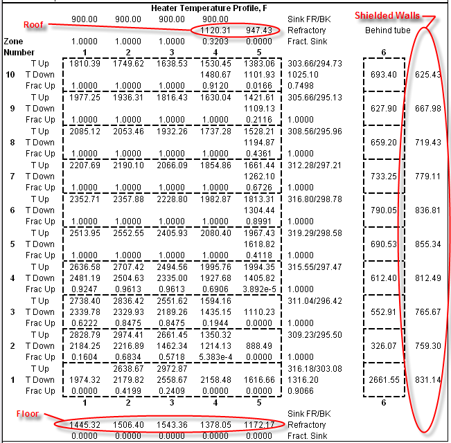
So for the floor, (1445.32 + 1506.40 + 1543.36 + 1378.05 + 1272.17)/5 = 1,429.06 °F
And for the walls, (831.14+759.3+765.67+812.49+855.34+836.81+779.11+719.43+667.98+625.43)/10 =
765.27 °F
And for the roof, we will use (1120.31 + 947.43)/2 = 1,033.87 °F
For the convections walls, we will assume the hot face temperature to be the average of the temperature in and the stack temperature, or (1662.83 + 469.77)/2 = 1,066.3 °F
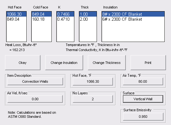
And the convection tube sheets at the same temperature, 1,066.3 °F
For the header boxes, we will use the average fluid temperature, ((221 + 250)/2 + 1,066.3)/ 2 = 650.9 °F
The convection breeching will be at the stack temperature, 469.77 °F
The stack transition will be at the stack temperature, 469.77 °F
To check the tube wall thickness assumptions that we made for the fired heater, we use API RP530.
The design data for the heater is as follows:
Tube: 4 ½” Sch 40 A106 Gr B pipe
Tube Average wall thickness: 0.237”
Design Pressure: 400 psig
Design Temperature: 700 °F
Corrosion Allowance: 0.125 “
API RP530 Tube Wall Calculator
This calculator uses curve fits of the stress values and formulas from the API RP 530 to calculate the minimum tube wall required for design life of 100,000 hours.For the ladders and platforms as required by API 560, we will need the following: Full 360 ° platform at hearth (floor) level to view burners.
Roof level platform for access to convection tubes, radiant tube pulling doors, and instruments located at bridgewall area.
Damper access platform at base of stack.
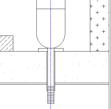
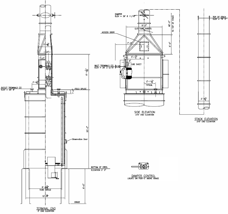
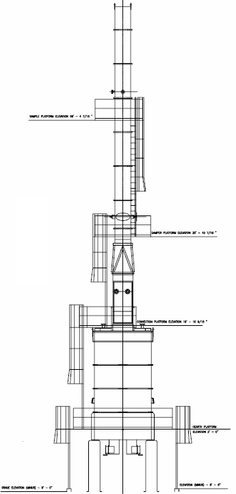
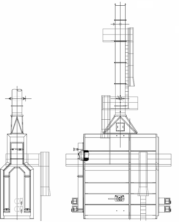
270 ° Platform at EPA required sample ports 2 diameters down from top of stack. The plan views would be similar to below:
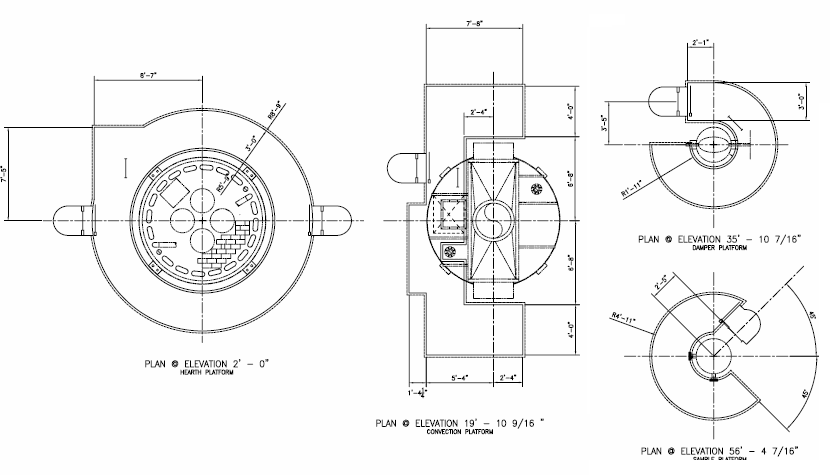
And the elevation view of the ladders and platforms would be similar to those shown below:
And lastly, we need to determine what instrument connections and other items are required to be located on the heater to meet API 560 requirements and normal practice.
(6) 1 ½” Couplings for Draft, (1) Floor, (2) Arch (bridgewall), and (1) Breeching, (1) before and (1) after damper in stack.
(4) 1 ½“ Couplings for Temperature, (2) arch, (1) Breeching, and (1) Stack
(1) 3” Flanged O2 Analyzer at Arch
(2) 3” Flanged Flue gas Analyzer connections, top of stack Other miscellaneous items:
(4) Observation doors
(2) Purge Steam Connections at floor
(1) Damper control located near grade
(1) Radiant tube pulling door
(1) Radiant floor access door
(1) Stack transition access door
(8) Fluegas corbels
(4) Port seals for terminal pipes
(20) port seals for bottom tube supports
Guidelines for Horizontal Cabin Fired Heater Design
For the purpose of demonstrating the methods below, we will assume a heater is required to meet the following data, which is the same as we used for the Vertical Tube Cylindrical Design:
- Service – Water Heater
- Duty – 12,730,300 Btu/hr
- Flow – 154,475 lb/hr
- Outlet Pressure – 85 psia
- Pressure drop allowed – 15 psi
|
Description |
Inlet conditions |
Outlet Conditions |
|
Percent Vapor, % |
0 |
0 |
|
Specific Gravity |
0.9552 |
0.9172 |
|
Viscosity, Cp |
0.2651 |
0.1811 |
|
Specific Heat, Btu/lb‐F |
1.0081 |
1.0293 |
|
Conductivity, Btu/hr‐ft‐F |
0.3950 |
0.3971 |
- Site Ambient Temperature – 80 °F
- Site Elevation – Sea Level
- Target Average Radiant Flux Rate – 10,000 to 12,000
- Target Efficiency – 85 to 87 %
- Burners Natural Gas, Low NOx configuration
- Fuel to have the following composition, % Volume:
- CH4 92.473
- C2H6 4.968
- C3H8 0.554
- C4H10 0.167
- C5H12 0.053
- C6H14 0.097
- N2 0.621
- CO2 1.067
Radiant Configuration Selection: For this second example, we will assume a horizontal cabin heater design is desired.
Preliminary estimate of surface in radiant section: To begin a design, you can assume that approximately 70% of the heat to be absorbed will be absorbed in the radiant section, and the remainder in the convection section.
Approximate surface = 0.70 * 12730300 / 10000 = 891 ft2
Deciding the initial tube size and layout: Since 4” nominal pipe size is normally the lower cost material and the most available pipe for a typical service, it is a good place to start.
(4.5” dia. * Pi * 12”)/ 144 = 1.178 ft2/ft is the area per foot of pipe 891/1.178 = 756 ft of 4” nominal pipe required for radiant section
So if we were going to design this heater as a horizontal tube cabin heater, we would need to rough out the number of tubes on the hip and the number of tubes wide in the convection section which will set the tube width in the radiant section.
Convection Section Preliminary Sizing: If we assume that the convection section will have 4 tubes wide (typical minimum for 4” nominal tubes) that will set the convection inside width at 4.5 spaces * 8” tube space = 36” inside insulation (assuming staggered tube arrangement).
The tube length will normally be the same as in the radiant section. If we assume the simplest tube support system will work, which is end tube sheets with returns located in external header boxes, then using the tube support maximum specified by API 560 of 35 tube diameters, the effective tube length will be 4.5 * 35 = 157.5”/12 = 13.125’, or 13ft.
API 560 requires that the shield (shock) tube section has 3 rows deep. The shield section always uses bare tubes. API 560 requires the first row flux to be included in the average heat flux density of the radiant section.
The remainder of the convection section tubes may be bare or with extended surface. Per API 560, the convection section must be designed to allow for two future rows of tubes. This code also requires that the convection section be designed with lanes for soot blowing, steam lancing or water washing, and these lanes must consider the future row requirement.
The convection section must be designed with corbels to minimize flue gas bypassing. API 560 does not specify how this design is to be accomplished, but the normal practice is a minimum of a corbel every other row. If the convection has end covers instead of tube sheets, then the return and bare tube beyond extended surface would be corbelled.
Since heater efficiency is very much enhanced with extended surface tubes, for our design, we will assume four rows of extended surface tubes.
For a cabin type heater the bottom row of shield tubes is normally centered on the centerline of the heater, unlike a box type heater where the first row is normally staggered.
There are two ways to locate the uppermost hip tube in a cabin heater design; it may be either on the same row as the lower shock tubes, as shown below:
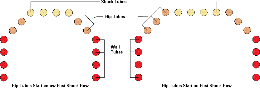
This allows different ways to adjust the tube width of the radiant section. But the primary difference is the type of tube support used, in those heaters requiring internal tube supports, i.e., those with a tube length greater than 35 tube diameters or more than 20 feet in length. A tube is considered a wall tube if the support is on the vertical wall and a hip tube if the support is on the sloped wall. The first row of shock tubes are normally supported by a double tube support hanging from the tube sheet supporting the second and third rows of the shock tubes. All of these tubes must be considered to be radiant tubes per API 560.
Radiant Section Preliminary Sizing: As explained in the preceding paragraph, the width of the radiant section width can be set by manipulating where the hip tubes start and how many hip tubes are used. This is important since for small cabin heaters, we need enough width to get the required burner centerline to tube centerline spacing to meet the API 560 Specifications, but we don’t want it to be any wider than needed so that we can get as much height as possible above the burners. If we assume the same efficiency that we had on the Vertical tube heater, 88.7%, then the release will be 12,730,300/.887 = 14,352,086 Btu/hr.
We will start by assuming four burners, with each burner having a normal release of 14,352,086/4 = 3,588,021 Btu/hr. Per API 560, the maximum burner release for each burner will then be 3,588,021 * 1.25 = 4,485,026 Btu/hr. Interpolating in the API 560 chart for burner to tube spacing gives us a 2’‐7 ½” from centerline of burner to centerline of the wall tubes and 3’‐11 ¼” from centerline of burner to centerline of shock tubes. Additionally API 560 requires 19’‐6” between opposing burners firing horizontally. Therefore this rules out our first thought of using a tube sheet to tube sheet design to avoid costly alloy tube support castings, since 13’ is not enough length for the two sets of burners.
The next choice on tube length would be 1.5 times the support to support distance of 13’, or a tube length of 13 * 1.5 = 19.5’.
Using a 4” nominal pipe, tube size, the surface per foot can be calculated as 4.5/12 * Pi * 1 = 1.1781 ft2/ft. And the number of tubes in the radiant can be estimated by using 891(from above)/(1.1781 * 19.5) = 38.8 tubes. We will round this up to 40 so that each side will be equal.
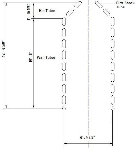
We will first start with the first hip tube starting below the shock row, and will assume 4 hip tubes total or 2 per side. This will give a hip width of three spaces on a 45° Angle, with each space being the standard two nominal diameters, or 8”. So the hip width = 3 * 8 * 0.7071 (Sine of 45°) = 16.9704”. This results in a tube centerline to tube centerline = 16.9704 + 3 * 8(convection tubes) + 16.9704 = 57.9408”.
However, from above, we need 2’‐7 ½” + 2’‐7 ½” = 63” for the burner to tube centerline, so if we add another tube to each hip, this will give us 57.9408” + 2 * 8 * 0.7071 = 69.2544”. Or if we start the hip tubes on the shock row and don’t add hip tubes, we would get 2 * ( 8 – 8 * 0.7071) + 57.9408 = 62.6272”, which is just over what we need. So for now, we will stick with 6 hip tubes, and a tube width of 69.2544”
We need approximately 40 tubes from above calculations, so this will leave us with 40 – 6 = 34 wall tubes, or 17 per side. From API 560, the floor to tube centerline , must be a minimum of 12”, so the floor to shock row height = 12 + 8 * (17 – 1) + 4 * 8 * 0.7071 = 162.6272” = 13’ – 6 5/8 “.
Burner selection: Since we have already sized some burners for the Cylindrical Design, and we are planning on the same number for the Horizontal Design, we can assume the spacing of the burners can be the same, at 26 7/8” apart. So If we set the lower burner at 13” above the floor, then the distance from upper burner to shock tubes will be = 162.6272” – 13” – 26.875” = 122.7522” which is greater than the 47.25” required by API 560.
The Radiant Fire Box: To proceed to the thermal design, we now have our firebox described as below.
The height of the firebox is 13.552, so the height to width ratio is 13.552/5.708 = 2.317 which is below the maximum allowed by API 560 of 2.75.
Number of tube side passes: The number of tube side passes or flow streams in the heater will be assumed as two. This will be increased or decreased during thermal design to meet pressure loss requirements.
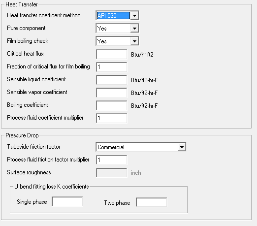
Thermal design of the heater:
We will use wrought return bends for this heater, which is common practice. The return bend with a center to center of 8“, would have an effective length 8 * Pi /12/2 = 1.0471’.
We are supporting one end of the tube with and end tube sheet, and the other with an internal support 13 ft from the refractory on the tube sheet end. Therefore the effective tube length is 19.5’, and the actual tube length will be 19.5{effective length} – (0.5 * 1.0471){return bend} + 3/12{insulation} + 0.5/12
{tube sheet} + 6/12{projection per API 560} = 19.7681’.
The tube length is less than the maximum of 40’ allowed by API 560 for this type of furnace.
To input this design in the HTRI Fxh program, we will need to make some adjustments on the inputs to allow for a cabin design which is not directly supported by the software. As we go through the inputs, we will make note of these modifications.
First we will select a Box Heater Input:
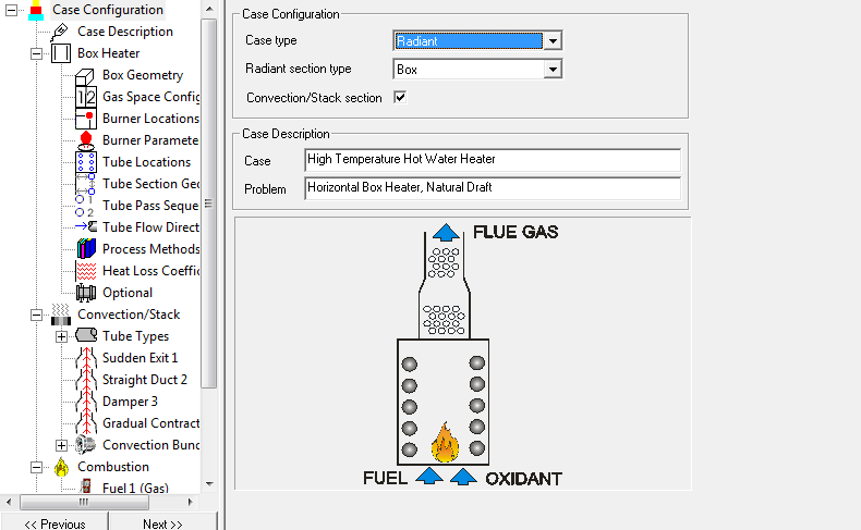
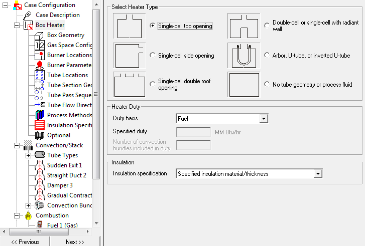
Heater Type:
For the Box Heater, we will indicate a single cell top opening.
Box Geometry: Since we must slightly modify the input to the Xfh software to allow for using a box design, we will take the length of the vertical wall = 12 {floor to first tube} + 8 * (17‐1) {tube spaces} + Tan 22.5° * 6.25 {wall to tube) = 142.589” = 11.8824’, and add it to the sloped hip length.
The hip length can be calculated as (40.875 {half the firebox} – 18 {half the convection}) / Sin 45° = 32.3501” = 2.6958’. So the total wall length = 11.8824 + 2.6958 = 14.5782’. Since we are entering it as a box instead of as a cabin configuration, we will reduce the wall length by the amount of the box roof
{offset}, and the height as 14.5782 – 1.9063 = 12.6779’.
Actual length of tube in box = 19.5{effective length} – (0.5 * 1.0471){return bend} = 18.9765’. If we add the return radius, 4”, and the tube radius, 2 ¼”, and the clearance for expansion, assume 6”, the total box length is then 18.9765 + (4 + 2.25 + 6)/12 = 19.9973, or 20’.
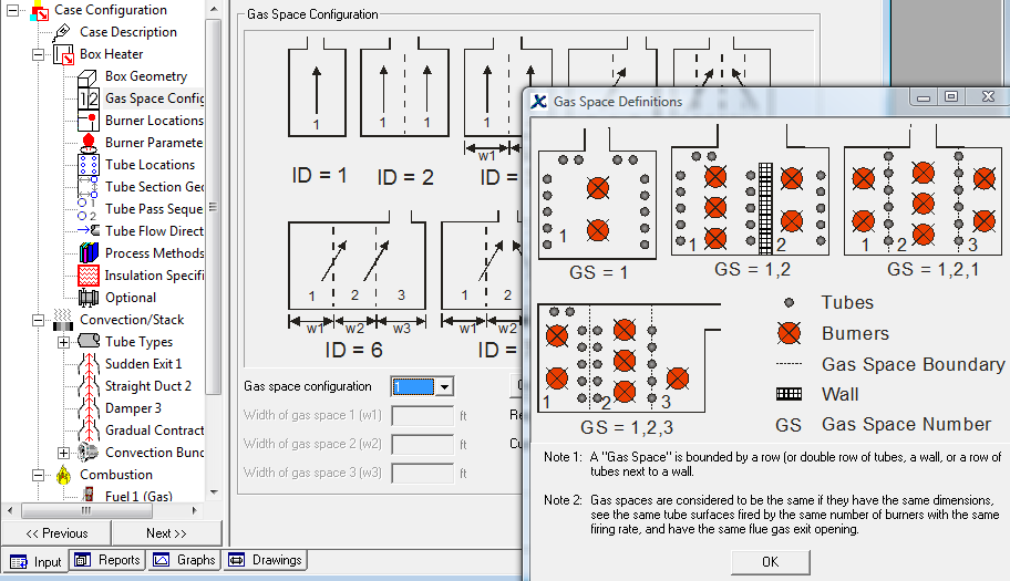
Gas Space Configuration: With a Gas Space Configuration selection of 1.
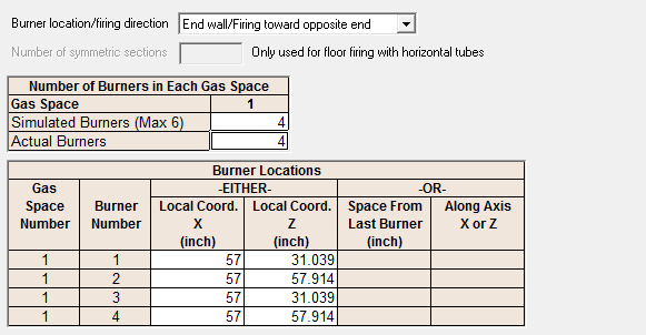
Burner Data: The burner locations Parameters can be described as below:
Tube Locations: Note that the hip tubes are input as roof tubes.
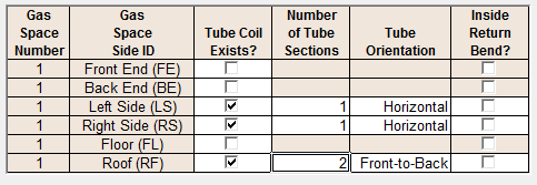
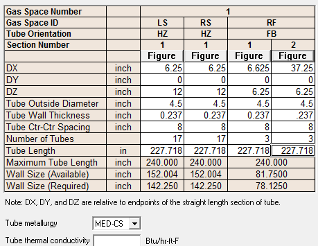
Tube Section Geometry: The tube data is entered as left side, right side, and roof.
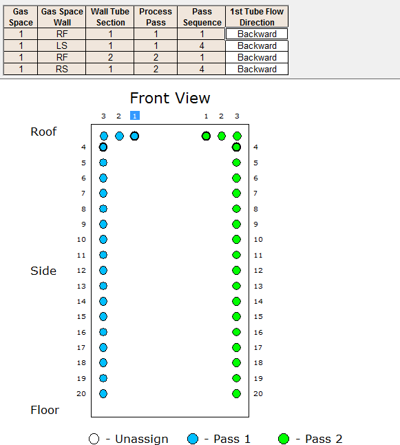
Tube Pass Sequence:
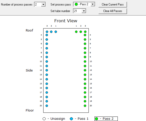
Tube Flow Direction:
Process Methods:
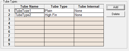
Tube Types:
We need plain tubes for the shock section and High Fin for the remainder of the convection.
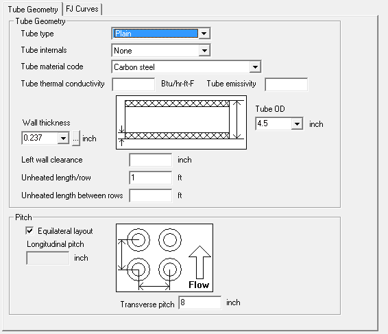
Tube Geometry for Type 1:
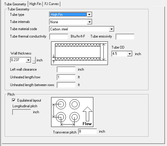
Tube Geometry Type 2:
Extended Surface:
Exit From Stack:
Stack Length:
We will assume the stack is 36’ and 2.75” diameter for initial run.
Damper:
Stack Transition:
Convection Section Bundle Geometry:
Convection Layout:
Combustion:

Fuel Inputs:
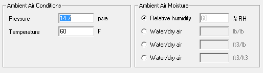
Ambient Air Conditions:
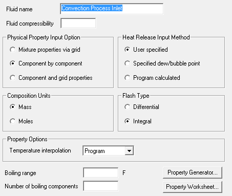
Process Feed properties:
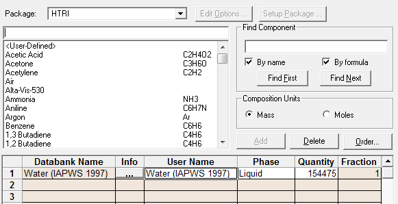
Composition:
Refractory System:
For our initial design, we will use the following refractory system. API 560 requires the outside casing not to exceed 180 °F with zero wind and 80 °F ambient temperature. The radiant floor can be 195 °F.
With this in mind, we will assume the following (All meeting API560):
Radiant Floor ‐ 2.5” Firebriick + 5” 1‐2‐4 LHV
Radiant Walls (shielded)‐ 1” 8# + 2”6# Ceramic Fiber
Radiant Walls (exposed) ‐ 1”8#+3”6# Ceramic Fiber
Radiant Walls (in firing zone) ‐ 1”8#+3”6# Ceramic Fiber+2.5” Firebrick
Convection Walls ‐ 1”8#+3”6# Ceramic Fiber
Header Boxes ‐ 2” Cerwool
Convection Breeching ‐ 1”8#+1”6# Ceramic Fiber
Stack Transition ‐ 1”8#+1”6# Ceramic Fiber
Stack – Unlined since at this efficiency temperature will be between 400 ° F and 700 °F as allowed by API 560
Plate Thicknesses:
We will assume the following plate thicknesses, which will be ultimately checked by structural engineer.
Radiant Floor – ¼”
Radiant Walls – 3/16”
Radiant/Convection Tube Sheet – 1/2”
Radiant /Convection End Covers – 3/16”
Convection Walls – 3/16”
Convection Breeching – 3/16”
Stack Transition – ¼”
Stack – ¼” Minimum
Check Volumetric Heat Release:
Burner Chamber = 8.497’ Volume = 74.8 x 19 = 1,421 ft3
Volumetric Heat Release = 14,352,086/1421 = 10,100 Btu/hr‐ft3 which is less than the 16,000 Btu/hr‐ft3 allowed by API 560.
Our Initial Thermal Design Run:
Our pressure drop is okay, so no need to modify tube passes. If we tried to go down to 1 pass, we would exceed allowed, so two pass is best fit.
Our flux rate is within our target, and our efficiency is better than target, so we should consider reducing the tube rows in the convection.

Final Thermal Design Run:
Stack Design:
API 560 [2.2.5] requires stack to be designed to achieve ‐0.10 at the arch of heater to assure negative pressure throughout. This design is to be based on 120 % of burner release, design excess air and design stack temperature, and maximum ambient air temperature. Normal practice is to use approximately 20‐ 25 ft/sec velocity in stack.
At 120 % burner release and design excess air, the flue gas flow will be 18,055 lb/hr and the stack temperature will be 425 °F. Ambient air temperature is 80 °F.
To recheck the burner sizing and spacing, the total release per our last run is 14.8636 MM Btu/hr , and the release per burner will be 14.8636/4 = 3.7159 MM Btu/hr. Per API 560, the size for each burner will be 3.7159 * 1.25 = 4.6449 MM Btu/hr. So the required horizontal spacing from tube centerline to burner centerline is 2’ – 8”. Our layout for the radiant section has 2’ – 10 5/8” which exceeds this minimum value. 19.28’ between opposing burners which we will be able to accomplish with our current layout.
A layout of the end wall with a typical burner design and adding typical steel support and base plates, would look similar to below:
To determine the tubes, fittings and finning needed for the design, we will use a simple layout of the coils. The convection coil would be as shown. Notice, that per API 560 we needed to include a cleaning lane or soot blower lane in the design.
We must also allow for two additional future convection rows when we layout our convection section.
Convection Tube Layout:
And the radiant section will be as we established previously. Note that the lower bare row of the shock tubes are not in the same triangular pattern as the remainder of the convection section. This is done to center this row of tubes to allow the hip tubes to connect to the row using the same tube spacing as the remainder of the radiant tubes.
Radiant Section Tube Layout:
At this point in the design of the fired heater, a general arrangement drawing would normally be created giving the overall dimensions of the heater and indicating the insulation to be used in the different areas. The structural steel at this point is simply added to the drawing based on previous designs of similar heaters. After the thermal and mechanical design has been completed, the general arrangement along with client specific requirements would be provided to the structural engineer for him to design the steel, selecting plate thicknesses, structural member sizes, etc. He would also develop the wind loading and base plate loading design parameters used for heater foundation design.
Now we need to go back and check or refractory (insulation) assumptions made earlier to assure they meet API 560 casing temperatures.
Radiant Floor ‐ 2.5” Firebriick + 5” 1‐2‐4 LHV
Radiant Walls (shielded)‐ 1” 8# + 2”6# Ceramic Fiber
Radiant Walls (exposed) ‐ 1”8#+3”6# Ceramic Fiber
Radiant Walls (in firing zone) ‐ 1”8#+3”6# Ceramic Fiber+2.5” Firebrick
Convection Walls ‐ 1”8#+3”6# Ceramic Fiber
Header Boxes ‐ 2” Cerwool
Convection Breeching ‐ 1”8#+1”6# Ceramic Fiber
Stack Transition ‐ 1”8#+1”6# Ceramic Fiber
Stack – Unlined
To check the heater refractory selection, we need to establish design hot face temperatures for each of the areas, and then calculate the cold face temperature for each area, using 80 °F and zero wind velocity per API 560.
So for the floor we will use the average exiting firebox temperature plus 200°F, 1269 +200 = 1,469 °F
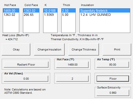
The cold face calculated exceeds the allowable per API 560, even though the materials meet the requirements of API, so we will need to consider if we should not follow API 560 for the floor.
For the shielded walls (behind the tubes), we will use the following for the hot face temperature.
Hot face temperature = Max. Tube Wall + (400 * Tube Space * Average Flux) / (2 * Tube Od * 10000) = 347 + (400 * 8 * 10479)/(2 * 4.5 * 10000) = 720 °F
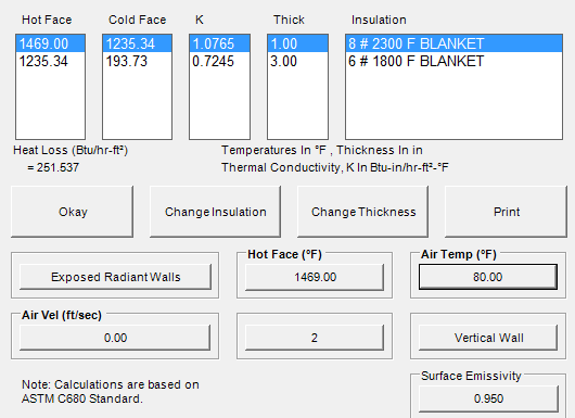
And for the exposed radiant walls, we will use Flue gas exit temperature plus 400 °F = 1269 + 400 = 1469°F.
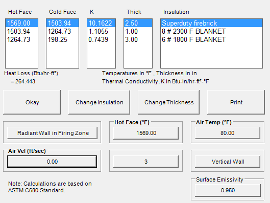
And for the exposed radiant walls in the firing zone, we will use 1269 + 500 = 1569°F.
For the convections walls, we will assume the hot face temperature to be the average of the temperature in and the stack temperature, or (1269 + 425)/2 = 847 °F
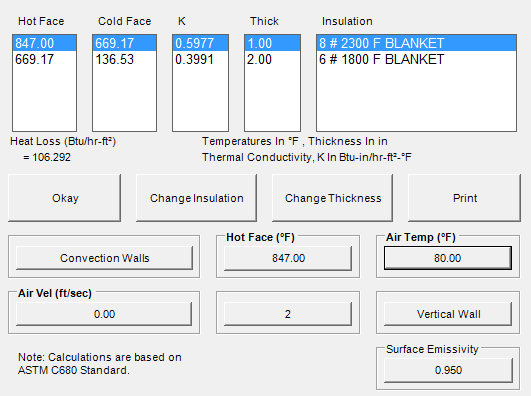
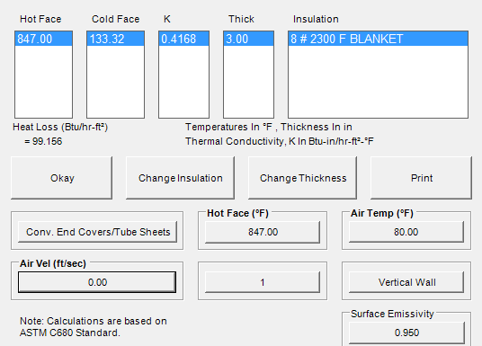
And the convection tube sheets and end covers at the same temperature, 847 °F
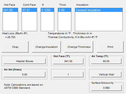
For the header boxes, we will use the average fluid temperature, ((221 + 250)/2 + 847)/ 2 = 541 °F
The convection breeching will be at the stack temperature, 425 °F

The stack transition will be at the stack temperature, 425 °F
To check the tube wall thickness assumptions that we made for the fired heater, we use API RP530. The design data for the heater is as follows:
Tube: 4 ½” Sch 40 A106 Gr B pipe Tube Average wall thickness: 0.237” Design Pressure: 400 psig
Design Temperature: 700 °F Corrosion Allowance: 0.125 “
API RP530 Tube Wall Calculator
This calculator uses curve fits of the stress values and formulas from the API RP 530 to calculate the minimum tube wall required for design life of 100,000 hours.For the ladders and platforms as required by API 560, we will need the following: Platform for access to convection tubes and instruments located at bridgewall area. Damper access platform at base of stack.
270 ° Platform at EPA required sample ports 2 diameters down from top of stack. The plan views would be similar to below:
And the elevation view of the ladders and platforms would be similar to those shown below:
And lastly, we need to determine what instrument connections and other items are required to be located on the heater to meet API 560 requirements and normal practice.
(6) 1 ½” Couplings for Draft, (1) Floor, (2) Arch (bridgewall), and (1) Breeching, (1) before and (1) after damper in stack.
(4) 1 ½“ Couplings for Temperature, (2) arch, (1) Breeching, and (1) Stack
(1) 3” Flanged O2 Analyzer at Arch
(2) 3” Flanged Flue gas Analyzer connections, top of stack Other miscellaneous items:
(4) Observation doors
(2) Purge Steam Connections at floor
(1) Damper control located near grade
(1) Radiant floor access door
(1) Stack transition access door
(8) Fluegas corbels
(4) Port seals for terminal pipes
Acknowledgements
This article was written by Mr. Jack Hardie of Conroe, Texas.
The article uses screen snapshots of following software applications:
- Xfh from HTRI
- WinHeat
- Online Calculators provided by Esteem Projects
Disclaimer:
The formulas and correlations presented herein are all in the public domain and are to be used only as a learning tool. Note that any product, process, or technology in this document may be the subject of other intellectual property rights reserved by sponsors or contributors to this site. This publication is provided as is, without any warranty of any kind, either expressed or implied, including, but not limited to, the implied warranties of fitness for a particular purpose, or non-infringement.
The formulas, correlations, and methods presented herein should not be considered as being recommended by or used by the sponsors of this site. The purpose of this site is educational and the methods may or may not be suitable for actual design of equipment. Only a fired heater design engineer is qualified to decide if a calculation or procedure is correct for an application.