Fans & Blowers
 |
Fans and blowers, as used in fired heater service, usually fall into one of the following categories. Each of these purposes are usually served by a different type fan. |
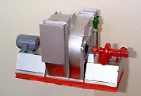
Forced draft (FD) fans are used in heater service to supply combustion air to the burner(s). They draw in oxygen rich ambient air and force it through the burner system for the combustion of fuel. They normally are not employed to move the flue gasses through the furnace setting, but in special cases, such as a positive pressure, single fan air preheat system, they may also provide the energy for this purpose.
The FD fan is normally handling clean, ambient air. One exception is when the air preheater is located upstream of the FD fan. In this case it is handling hot clean air. When handling clean ambient air, the basic parameter of fan selection is the fan's efficiency. Backward inclined air foil, single thickness backward inclined, or forward curved wheel fans usually offer the best selection. On very low pressure drop applications, axial flow fans may suffice. On high pressure drop heaters such as single fan air-preheat types, it is sometimes necessary to employ a radial or modified radial wheel fan.
A typical Forced Draft Fan specification might include:| Construction | Small | Medium | Large | |
| Relative Size | < 10,000 cfm | 10-50,000 cfm | > 50,000 cfm | |
| All Welded Housing | Yes | Yes | Yes | |
| Min Housing Thickness | 10 ga | 3/16" | 1/4" | |
| AMCA Arrangement | 4, 7, or 8 | 4, 7, or 8 | 1, 7, or 8 | |
| Wheel Type | BI, BIA, or FC | BI, BIA, or FC | BI, or BIA | |
| Accessories | ||||
| Door | Yes | Yes | Yes | |
| Drain | Yes | Yes | Yes | |
| Coupling | Arrg 7 & 8 | Arrg 7 & 8 | Yes | |
| Coupling Gaurd | Yes | Yes | Yes | |
| Shaft & Bearing Gaurd | Yes | Yes | Yes | |
| Inlet Silencer | If Req'd | Probably | Yes | |
| Inlet Damper | If Req'd | If Req'd | If Req'd | |
| Outlet Damper | If Req'd | If Req'd | If Req'd | |
| Sleevoil Bearings | No | Possibly | Probably | |
| Bearing Temp. Detectors | No | Possibly | Probably | |
| Inlet Filter | Possibly | Possibly | Possibly | |
| Inlet Guard | Yes | Yes | Yes | |
| Inlet Box | If Req'd | If Req'd | If Req'd | |
| Damper Operator | Possibly | Possibly | Probably |
Induced Draft Fans:
Induced draft (ID) fans are generally used to pull the flue gas from the heater and discharge it to atmosphere directly or through an air preheater. Applications where this discharge is direct are unusual. An example might be where a fired heater was also being used as a waste gas flare. The normal use of the ID fan is on a two fan air preheat system. A single ID fan system might work but many factors would favor the FD fan single fan system over the ID fan. The cfm handled and the cold clean versus hot dirty gas at the fan favor the FD system.
On two fan air preheat systems the fan selection is usually dictated by system pressure drop and type of fuel being burned. Centrifugal fans are almost always used since nothing but the wheel and shaft are actually exposed to the hot gas stream. BIA, BI, and FC radial and modified radial wheels are employed. On heaters firing heavy oils, only the radial or modified radial wheel should be considered. For hot clean gas, all five might be reviewed, but efficiency probably will favor the BIA and BI.
An important factor in the selection of both the FD and the ID fans for fired heaters is that in both cases they are employed in continuous operation. For this reason, they should almost always be selected to run direct driven by their driver. The reliability of flexible couplings over v-belts is sufficient to outweigh the latters great variability in speed selection. Therefore, it is often necessary to review a number of possible fan selections to find the best "fir" for a particular application. AC motors offer very few speed choices and the price goes up rapidly with decreases in speed.
A typical Induced Draft Fan specification might include:| Construction | Small | Medium | Large |
| Relative Size | < 10,000 acfm | 10-50,000 acfm | > 50,000 acfm |
| All Welded Housing | Yes | Yes | Yes |
| Min Housing Thickness | 10 ga | 3/16" | 1/4" |
| AMCA Arrangement | 4, 7, or 8 | 7 or 8 | 1, 7, or 8 |
| Wheel Type | RAD | RAD or Mod RAD | RAD or Mod RAD |
| Accessories | |||
| Door | Yes | Yes | Yes |
| Drain | Yes | Yes | Yes |
| Coupling | Arrg 7 & 8 | Arrg 7 & 8 | Yes |
| Coupling Gaurd | Arrg 7 & 8 | Arrg 7 & 8 | Yes |
| Shaft & Bearing Gaurd | Arrg 7 & 8 | Arrg 7 & 8 | Yes |
| Inlet Box | If Req'd | Probably | Yes |
| Inlet Box Damper | If Req'd | If Req'd | If Req'd |
| Outlet Damper | Possibly | Probably | Probably |
| Insulation Studs | If Req'd | If Req'd | If Req'd |
| Hi Temp Construction | If Req'd | If Req'd | If Req'd |
| Bearings : |
No | Possibly | Yes |
| No | Possibly | Perhaps | |
| No | Possibly | Perhaps | |
| No | Perhaps | Yes | |
| No | Perhaps | Yes |
Purge Fans:
The purpose of the purge fan is to discharge from a heater setting any potentially explosive gas mixtures prior to lighting of the burners. Purge fans are especially desirable on heaters that are shut down and relighted on a regular basis. Heaters employing FD or ID fans do not normally require additional purge fans. Running the FD or ID fan usually will purge the system.
Natural draft heaters, however, are often fitted with purge blowers. When a cold heater experiences a light off failure, it can build up a potentially explosive gas mixture. As the heater setting is cold, there is no "natural draft" available to remove these gases. The purge fan is normally a small low pressure drop axial fan.
It is important to protect these fans when they are not being used, since the radiant heat they may be exposed to would destroy the fan. A butterfly valve is often used to shut the fan off from the hot gases in the firebox. Some purge fan applications require the injection of purge air at multiple entry points. It is necessary to determine the cost and advantage of multiple fans versus a single fan with manifolds in these systems. With a duct system, a centrifugal fan would normally be required because of the ducting resistance in the manifold.
A typical Purge Fan specification might include:| Construction | Small | Medium | Large |
| Relative Size | Up To 1,000 cfm | 1-5,000 cfm | 5,000 cfm & Up |
| Fan Type (Lo Dp) | Axial | Axial | Axial or Cent |
| Fan Type (Hi Dp) | Cent. | Cent. | Cent |
| All Welded Housing | Yes | Yes | Yes |
| AMCA Arrangement(Cent. Only) | 4 | 4 | 4 |
| Accessories | |||
| External Lube Lines | Yes | Yes | Yes |
| Outlet Damper | Yes | Yes | Yes |
| Inlet Guard | Yes | Yes | Yes |
| Inlet Rain Hood | Yes | Yes | Yes |
| Drain (Cent. Only) | Yes | Yes | Yes |
| Damper Operator | Possibly | Possibly | Possibly |
Fan Selection:
The actual selection of a fan is almost always best left up to the fired heater designer, who working with the various fan vendors can establish the fan that best fits the needs of the application at hand. The specifying engineer, on the other hand, needs to clearly specify the level of quality he expects in his heater fan. This is normally covered in the specifications under construction and accessories.
It is important to understand the the nature of the application and tailor specifications accordingly. An accessory like a sleeve oil or forced lube bearings are well worth the cost on a large, hi-temperature ID fan, but on a small FD or purge fan they are not needed and almost certainly not obtainable. The bearing, let alone, the oil system would probably cost more than a complete spare fan.
Typical fan efficiencies:| Backward Inclined Airfoil (BIA) | Static efficiency to 85% |
| Backward Curved (BC) | High efficiency to 83% |
| Backward Inclined (BI) | Static efficiency to 80% |
| Radial Blade (RAD) | Static efficiency to 78% |
| Radial Tip (RT) | Static efficiency to 78% |
| Forward Curved (FC) | 55-65% static efficiency |
| Axial Flow | 35-50% static efficiency |
Disclaimer:
The formulas and correlations presented herein are all in the public domain and are to be used only as a learning tool. Note that any product, process, or technology in this document may be the subject of other intellectual property rights reserved by sponsors or contributors to this site. This publication is provided as is, without any warranty of any kind, either expressed or implied, including, but not limited to, the implied warranties of fitness for a particular purpose, or non-infringement.
The formulas, correlations, and methods presented herein should not be considered as being recommended by or used by the sponsors of this site. The purpose of this site is educational and the methods may or may not be suitable for actual design of equipment. Only a fired heater design engineer is qualified to decide if a calculation or procedure is correct for an application.