Tubes, Pipe, & Fittings
Selecting the heater tube material and size to use in a heater design is really a matter of experience. As you work with different fired heaters for different services, you develop a knowledge of what fit before in a similar design, so you know where to start with a new design. But a few general rules can be used to start the selection.
For the typical, general purpose heater, using standard pipe sizes, the 4" pipe size will normally work out to be the most economical pipe size. The cost will generally go up with a smaller or larger pipe size. Likewise, a one or two pass heater will normally work out best. Using the flux rate, for the radiant section, that you desire for the furnace, and assuming 70% of the heat is absorbed in the radiant section, you can make some preliminary pressure loss estimates to get a preliminary tube size to start with.
In a similar manner, you can make some preliminary estimates to determine what the design metal temperature for the heater tubes need to be. With this temperature, you would select the least material that is good for the temperature. Eventual analysis may show that a higher alloy and a thinner wall may be more economical, so running calculations with several materials is always wise.
Typical generic, pipe, and tube specifications used for heater tubes:| Generic Specification | Pipe Specification | Tube Specification |
| Carbon Steel | A 106 Gr B | A 178 A |
| 1¼ Cr ½ Mo | A 335 Gr P11 | A 213 T11 |
| 2¼ Cr 1 Mo | A 335 Gr P22 | A 213 T22 |
| 5 Cr ½ Mo | A 335 Gr P5 | A 213 T5 |
| 9 Cr 1 Mo | A 335 Gr P9 | A 213 T9 |
| 18 Cr 8 Ni | A 312 TP 304 | A 213 TP 304 |
| 16 Cr 12 Ni 2 Mo | A 312 TP 316 | A 213 TP 316 |
| 18 Cr 10 Ni Ti | A 312 TP 321 | A 213 TP 321 |
| 18 Cr 10 Ni Ti | A 312 TP 321H | A 213 TP 321H |
And other, more exotic materials for special furnaces are used as may be needed. The wall thickness required is normally calculated by using the API RP530 recommended practice, with the rupture allowable stress for 100,000 hours design life or the elastic allowable stress being used depending on the design tube wall temperature.
Tube Wall Thickness:For Elastic Design (lower temperatures)
And,
For Rupture Design (higher temperatures)
And,
Where,
| ts = Stress thickness, in |
| Pe = Elastic design pressure, psig |
| Pr = Rupture design pressure, psig |
| Do = Outside tube diameter, in |
| Se = Elastic allowable stress at design temperature, psi |
| Sr = Rupture allowable stress at design temperature, psi |
| tm = Minimum thickness including corrosion, in |
| CA = Corrosion allowance, in |
| F = Corrosion fraction as a function of B and n |
| Where, |
| B = CA/ts |
| n = rupture exponent at design temperature |
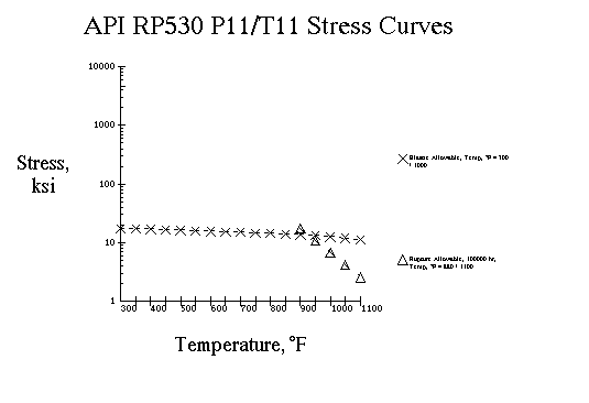
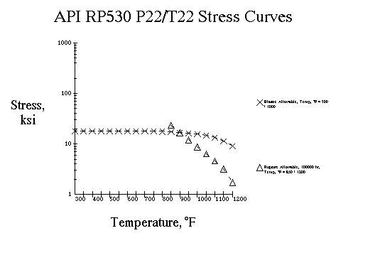
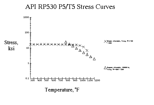
The tube metal temperature can be calculated as described in "Heat Transfer" section, under "Tube Wall Temperature Calculation" in this material. From this temperature, we can select the stress values from the following curves.
Carbon Steel: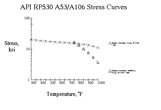
¼ Cr ½ Mo:
2¼ Cr 1 Mo:
5 Cr ½ Mo:
9 Cr 1 Mo:
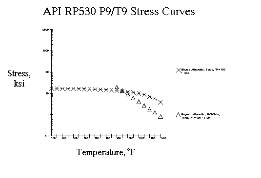
18 Cr 8 Ni:
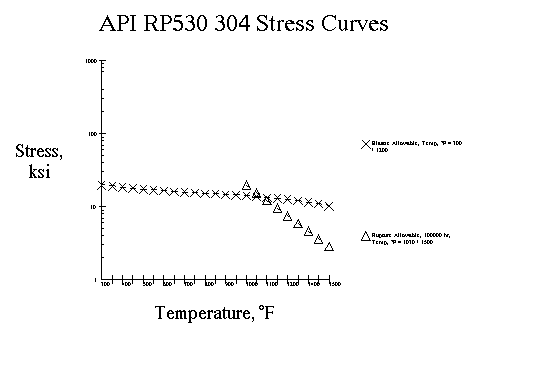
16 Cr 12 Ni 2 Mo:
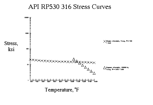
18 Cr 10 Ni Ti:
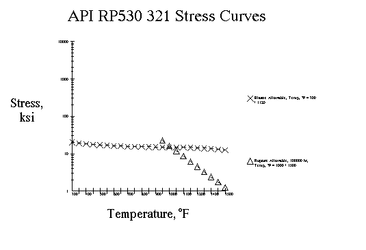
18 Cr 10 Ni Ti:
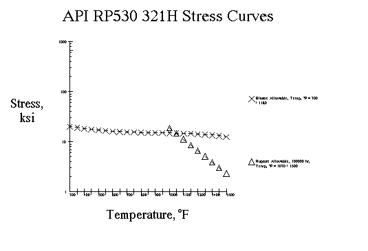
Using the above stress values and formulas, we can now calculate the minimum wall thickness for a tube.
A little bit of confusion over why a pipe is called a tube, when it is in a heater, might be expected. But usage dictates that the heat transfer tubes be referred to as tubes, heater tubes, or furnace tubes, regardless of whether they are manufactured from materials specified as tubes or as pipes.
But, the usage confusion goes even deeper, since the spacing from the radiant tube center line to the inside of the refractory is generally 1.5 nominal tube diameters and the centerline to centerline of the tubes in normally 2 nominal tube diameters. Of course in this case, nominal tube diameters is really referring to nominal pipe diameters or "Iron Pipe Size"(IPS). Tubes don't have a "nominal" diameter, but rather they have an outside diameter(od) and an inside diameter(id). Of course, pipe also has an od and an id, but the legacy pipe descriptions of 2"(2.375"), 3"(3.5"), 4"(4.5"), etc., pipe sizes, still persist to this day. As well, the designation of pipe schedules such as 40, 60, 80, etc. are still in common use today. Therefore, many US programs still cater to this usage by including built in routines to convert these designations to od, id, and wall thickness which must be used in the formulas.
So even if you are designing a furnace in Europe, and you are using 6.625 inch od tubes, you would most likely still set the tube centerline to wall dimension to 1.5 IPS(or nominal diameters), or 1.5 * 6 = 9 inches. Likewise you would probably set the centerline to centerline tube spacing at two times the IPS(or nominal diameter), 2 * 6 = 12 inches. This also might be because the rolling equipment for the return bends exist for these "standard" 180° returns, or the tube support casting patterns may exist for this standoff. All of these constraints need to be considered when setting the dimensions of the furnace during the design.
When using tubes with the OD of a standard pipe size or using piping specifications, you would normally select a standard return bend to return the flow in a tube to the next tube. These returns bends are normally manufactured in two turning radii, called "short radius" and "long radius". The short radius return refers to a 180° return bend using a radius of one nominal diameter, ie, a 4" pipe size return has a radius of 4", and a 6" has a radius of 6", etc. The "long" radius bend has a radius equal to 1.5 nominal diameters so a 4" return has a radius of 6" and a 6" has a radius of 9". These standard returns are manufactured in most of the pipe schedules and are also available in "minimum wall" specifications.
Typical generic and pipe specifications used for return bends:| Generic Specification | Pipe Specification |
| Carbon Steel | A 234 WPB |
| 1¼ Cr ½ Mo | A 234 WP11 |
| 2¼ Cr 1 Mo | A 234 WP22 |
| 5 Cr ½ Mo | A 234 WP5 |
| 9 Cr 1 Mo | A 234 WP9 |
| 18 Cr 8 Ni | A 403 WP304 |
| 16 Cr 12 Ni 2 Mo | A 403 WP316 |
| 18 Cr 10 Ni Ti | A 403 WP321 |
| 18 Cr 10 Ni Ti | A 403 WP321H |
If using standard pipe fittings manufactured to standard pipe schedules, you would assume 80% of the standard wall thickness. If you are bending tubes or pipe for the application, you would need to calculate the thinning in the bend. The following calculator estimates the ratio of that thinning.
Pipe-Wall Thinning In Bends:Tube Length Selection
Now that we have selected a tube diameter, material, wall thickness, and tube spacing, we need to decide what length the tubes should be. Pipe and tubes are manufactured in random lengths, ie, since the billet size varies, the actual length of the tube that is extruded, from a billet, varies from one tube to the next. For lower cost materials, it is usually cheaper to scrap pieces of tube, then it is to make center welds to try and use all the material. But another high cost factor involved with the length is the supports and guides for the tube in the furnace.
For vertical tubes, usually the overall furnace shape and size dictate the best tube length.As an example, for cylindrical radiant sections a length to diameter ratio of 3:1 might be the maximum desired, so the number of tubes and the length is balanced to achieve this ratio, while obtaining the surface required to meet the flux rate that is desired. The support and guide requirement varies depending on whether the tubes are supported from the top(hung) or bottom of the tubes.
In the horizontal tube furnace, the overall shape and size also figure into the equation. But, within these constraints, the span between supports must be considered. If the user has not specified a maximum span, then generally you would not want to exceed 35 tube OD's. This has been a general industry "not to exceed" rule of thumb used for many furnace designs. But care should be taken to consider the service and wall temperature of the tubes. Once you have determined the span between supports, the tube length would be selected to use the minimum number of supports, while avoiding unnecessary centerwelds, if centerwelds are allowed by user. All of this must be balanced with the fact that the pressure loss in the tubes is increased dramatically in the returns, so generally you want the longest straight tube possible. The pressure loss in the returns is reviewed in the "Process" section , under "Intube Pressure Drop".
Disclaimer:
The formulas and correlations presented herein are all in the public domain and are to be used only as a learning tool. Note that any product, process, or technology in this document may be the subject of other intellectual property rights reserved by sponsors or contributors to this site. This publication is provided as is, without any warranty of any kind, either expressed or implied, including, but not limited to, the implied warranties of fitness for a particular purpose, or non-infringement.
The formulas, correlations, and methods presented herein should not be considered as being recommended by or used by the sponsors of this site. The purpose of this site is educational and the methods may or may not be suitable for actual design of equipment. Only a fired heater design engineer is qualified to decide if a calculation or procedure is correct for an application.